Categories
Uncategorized

Rugged Parametric Box in OpenSCAD

Universal Parametric Rugged Box by Rainer Backes is perfect. Read more below if you need to.

Universal Parametric Rugged Box by Rainer Backes

I mentioned “Rugged Boxes” a bit in my Hardware Gridbox post, but the idea is basically a small box with a latch that is rugged, so it’s like a tiny Pelican case that you can print yourself.

It’s the sort of thing that if you want one a specific size for a specific use that someone else also needs, you might find it easily… but if you want it a custom size just for your specific application, well… you need to be able to adjust the design. There are a bunch of parametric designs that work with Fusion 360 (which I do not use) and I don’t know if Rugged Box (Parametric) by Whity is the original but it’s definitely quite popular.

Here’s an 80x80x60 version I printed, but I wanted something smaller. I tried this one but didn’t like it. So finally, we’ve got one that ticks all the boxes!

Universal Parametric Rugged Box by Rainer Backes is perfect. And by “perfect” I mean it’s written in OpenSCAD, and it works. At least my first print worked, as you can see by the photos. I haven’t pushed the design too hard yet, but being done in OpenSCAD means I can go crazy with it.

This saves me the trouble of having to write my own, which I did start working on. While I do enjoy designing objects I also enjoy finding code that someone else wrote that does exactly what I need. It looks like Rainer has a bunch of models written in OpenSCAD, so I may need to dig through the others for inspiration. Thanks, Rainer Backes!

Categories
Uncategorized

OpenSCAD Viewing Angles

I’ve found that more and more I am exporting images from OpenSCAD, and while in the past I was satisfied with just spinning the object to an angle and exporting a PNG file, I’m now doing more step-by-step things where I want consistency and don’t want things jumping around. Instead of carefully setting the view with the mouse and doing all the exports, I now set the viewing parameters directly in the file, because you can do that in OpenSCAD…

Time to go back to the OpenSCAD User Manual! While the Cheat Sheet is an excellent resource, I find myself hitting up the manual a lot more frequently lately. The Cheat Sheet will show you this of course:

$vpr viewport rotation angles in degrees
$vpt viewport translation
$vpd viewport camera distance
$vpf viewport camera field of view

And that’s what we need! So over to the manual section for $vpr,_$vpt,_$vpf_and_$vpd.

Pop open that Viewport-Control in the Window menu and look at that… it shows you values and you can change them…

(Note: You can also set the aspect ratio, and lock it. Sweet!)

But the real powerful bit is that you can just set those parameters in your code. When you preview your code it will set those values and you get the same viewing angle, rotation, distance and field of view each time. Brilliant!

You can see my commented out code for the bottom versus top view on line 37.

I love finding stuff like this and them implementing it into my code… It’s probably not some amazing killer feature, but it’s one more nicety that helps me keep things consistent and adds a bit more power to what I can do with OpenSCAD.

Categories
Uncategorized

Circular Positioning in OpenSCAD

This post is about a problem… it’s about looking at a problem from the wrong angle, and eventually realizing it.

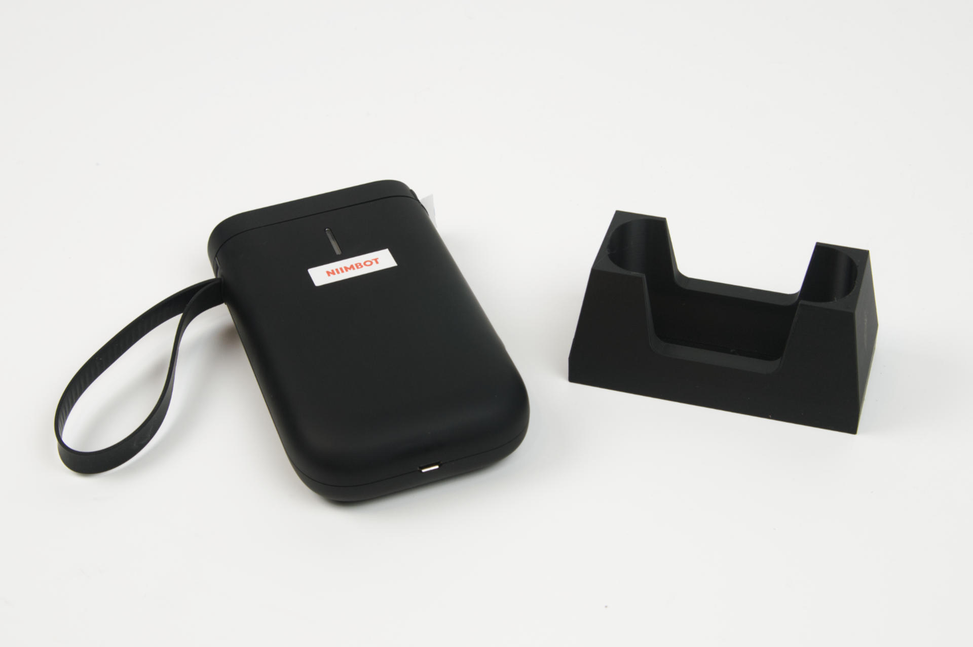
I wrote some code in OpenSCAD, and then I wanted to change something and I could not figure out how to get the positioning right. I should confess I am terrible at maths. In school I took geometry, but never did calculus or trigonometry, and know almost nothing about those areas of mathematics.

Since I tend to work in Cartesian coordinate systems I think about moving things in X and Y. Left, right, up, down… Sure, there are angles, but they can be difficult. But maybe they shouldn’t be…

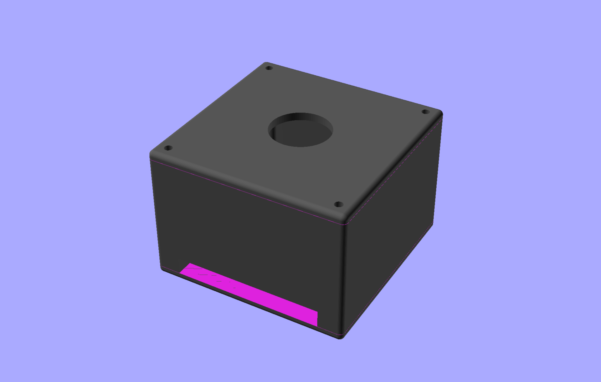
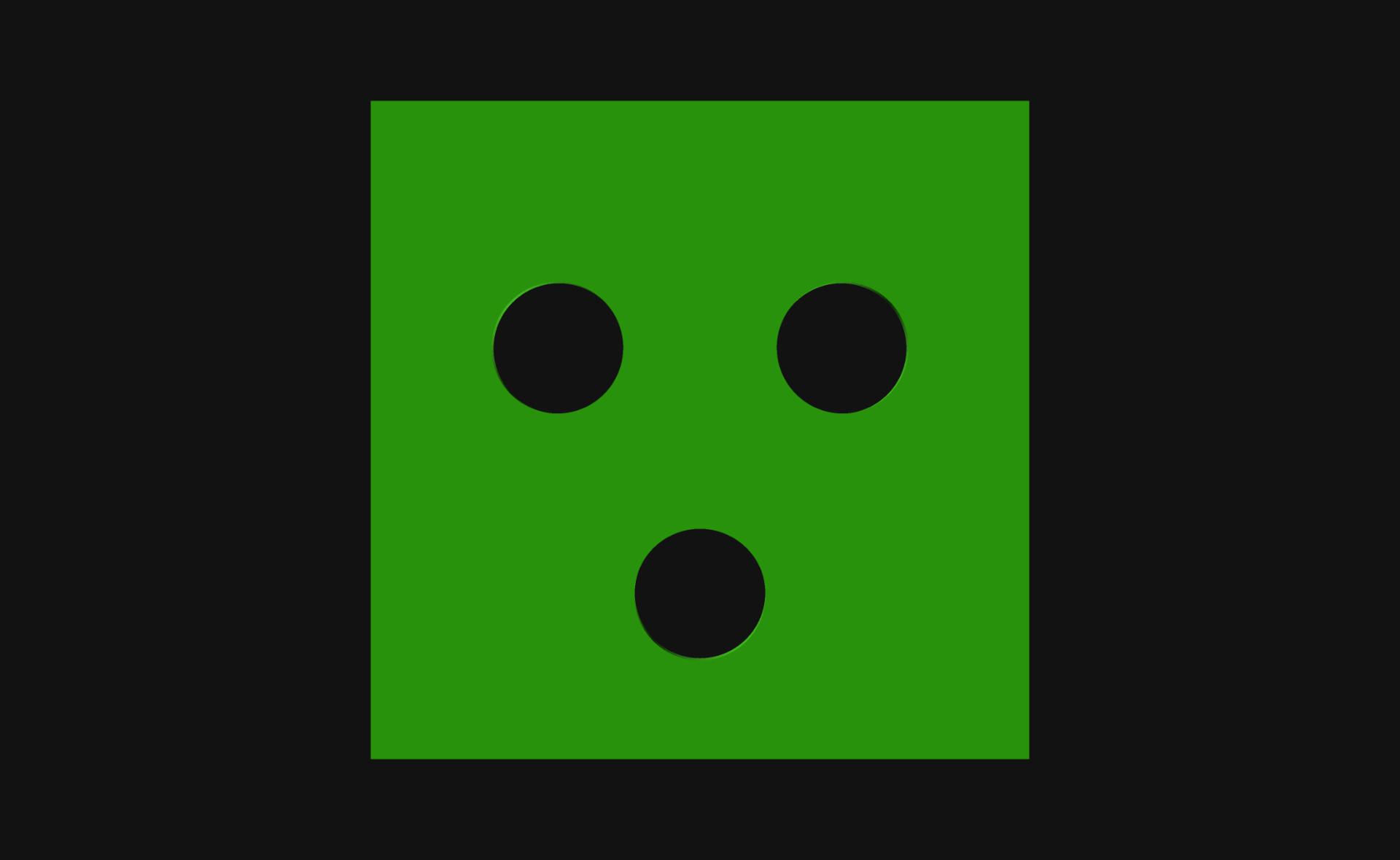
Here’s what I wanted to do: Create a circle with three smaller circles evenly placed into a triangle. Now typically in OpenSCAD I move things around in the X and Y and for the mostly rectilinear things I design (mostly enclosures) that’s simple, but circles can get weird. So what I tried to do was move each of the holes along the X and Y axes, but I could not get them evenly spaced…

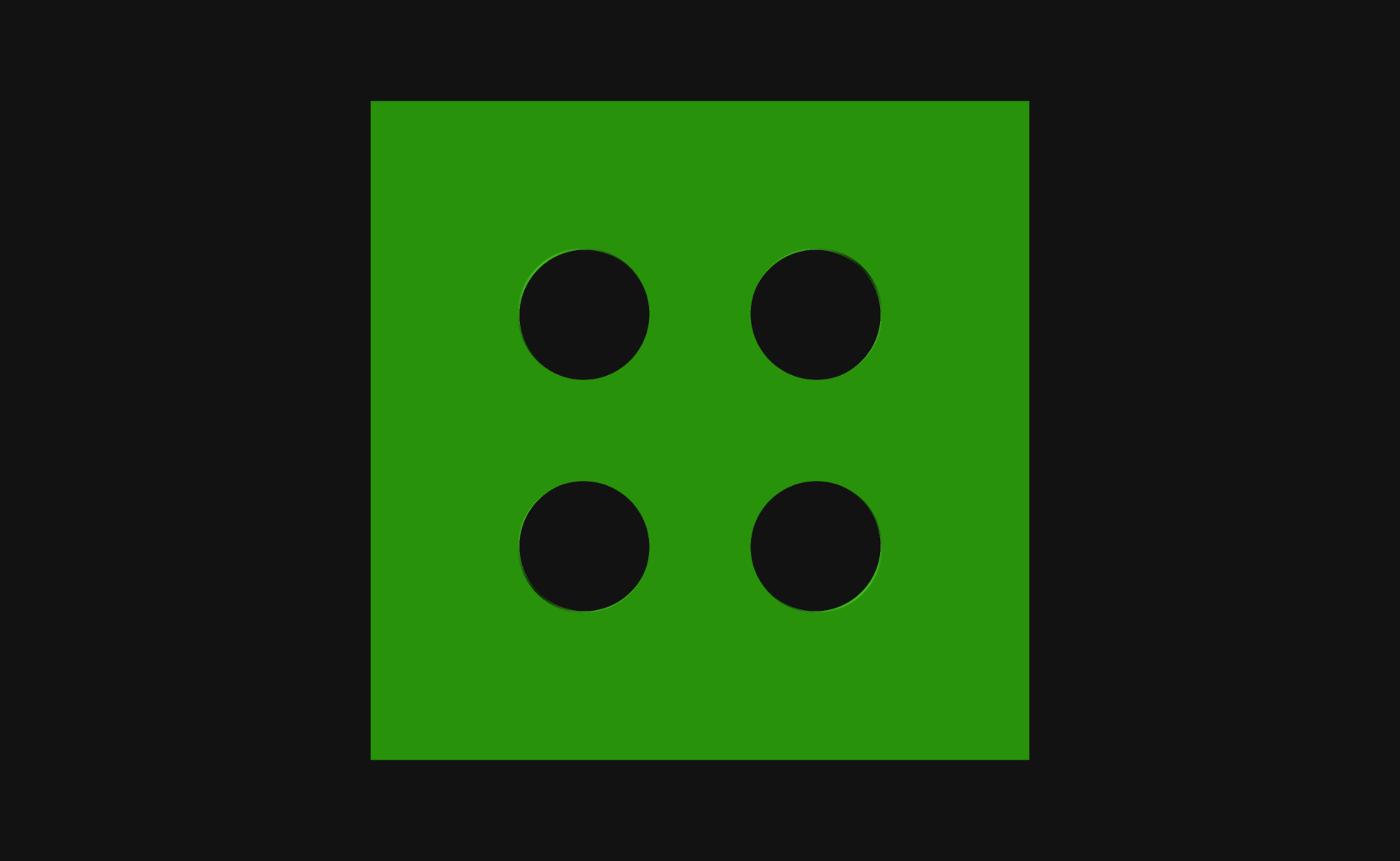
See, this is easy for me. Four things, evenly spaced. Everything moves from the center an equal amount in X and Y. My simple maths brain has no issue with this. I’m so used to doing it this way I can bang it out without any thought. But this way (while simple) is sometimes not ideal.

As is often the case, I took to Mastodon with my problem, because there are people there much smarter than I am… Luckily @GeekAndDad was on the case! While he was busy doing the hard math I was distracted with some other projects… but when I returned I realized I knew how to do it… because I did it ten years ago! Check out this post about Derby Wheels.

Okay, so I did it before, but didn’t have easy access to the code I had written, but remembered how it worked, so I banged this out:


// Position things in a circular pattern in OpenSCAD

$fn=100;

howMany    = 3;
distance   = 10;
holeSize   = 10;
startAngle = 30;

difference() {

    // create the object
    translate([0,0,0])
        cylinder(d=40, h=3, center=true);

    // loop around in a circle and difference some holes
    for(variable = [startAngle : 360/howMany : 360+startAngle]) {
        rotate([0,0,variable])
            translate([distance,0,0])
                cylinder(d=holeSize, h=3.1, center=true);   
    }
}

(You can also find this code in my gists repository.)

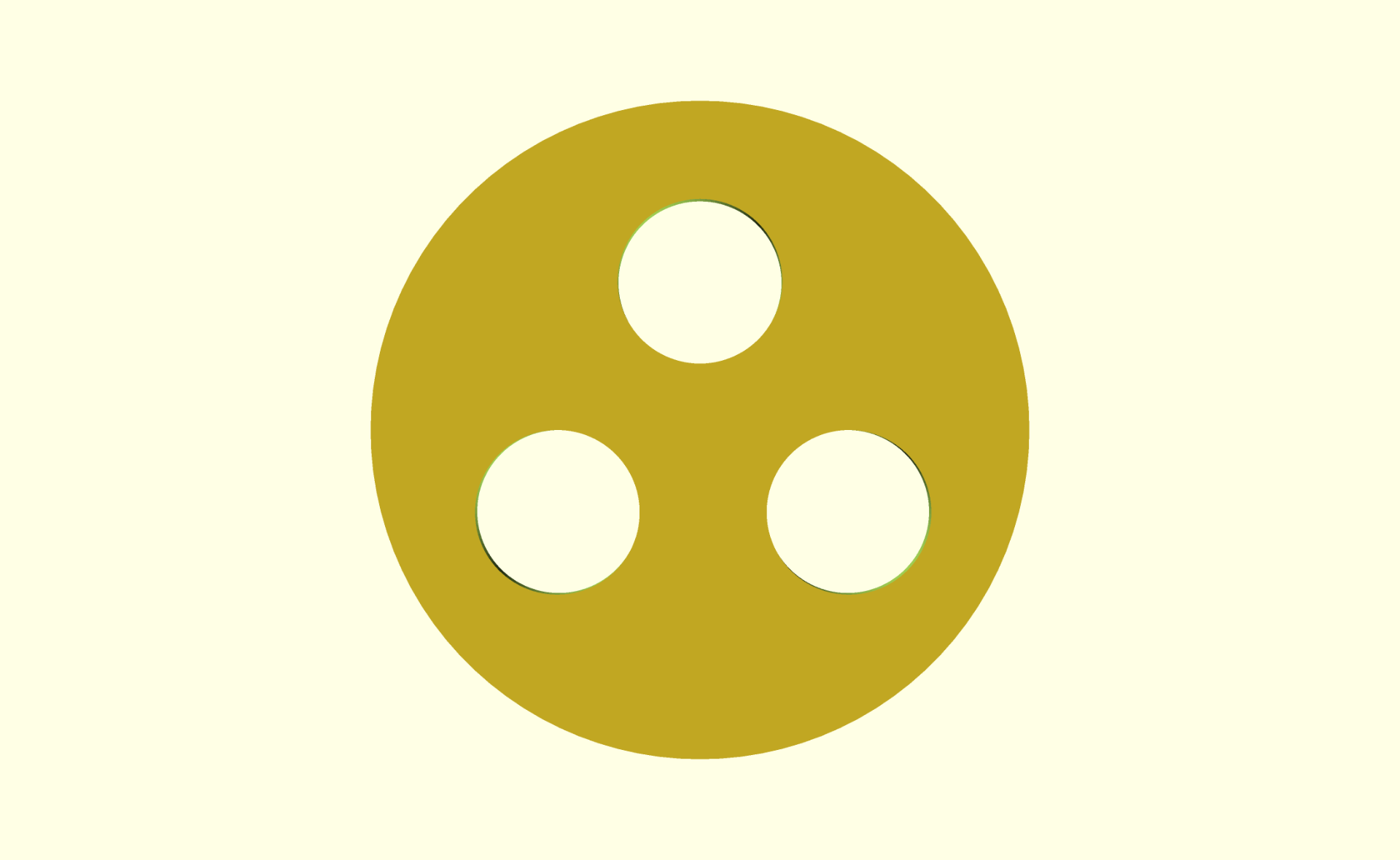
Here we go! Three holes, evenly spaced… We do this by rotating around the center and placing the hole X number of units from the center, every X number of degrees. You can set the number of holes howMany, the distance from the center, and of course the holeSize and also the startAngle which helps rotate the whole set into something that matches up properly.

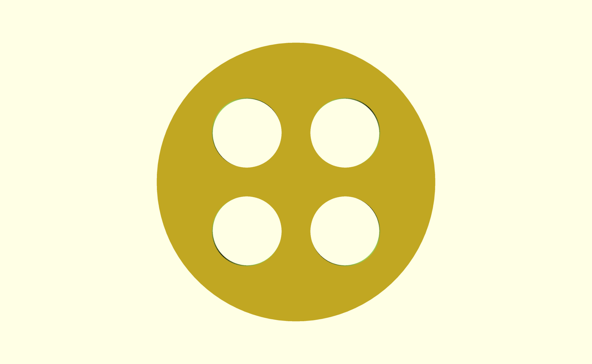
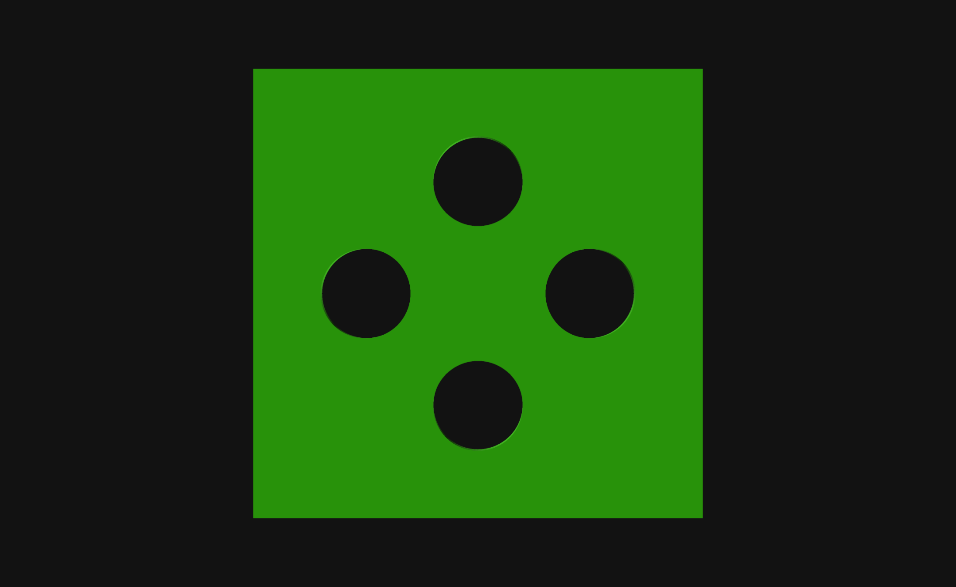
Hey, you can even do four holes! They are all still evenly spaced from the center…

You can do seven holes… The bit with 360/howMany does the maths to determine how many degrees there are before adding another hole.

Heck, you can even do just two. Want them top and bottom instead of left and right? Just change the startAngle appropriately.

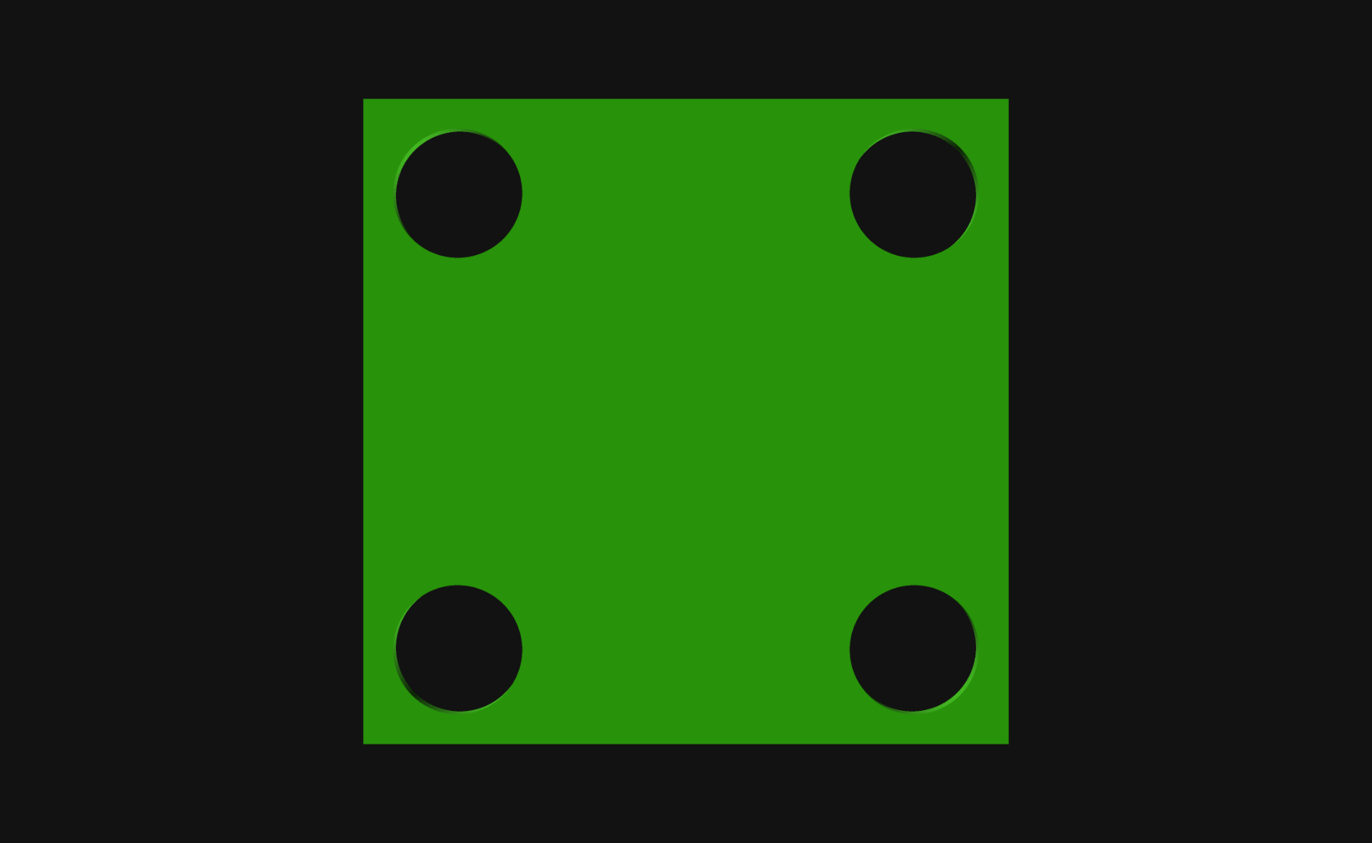
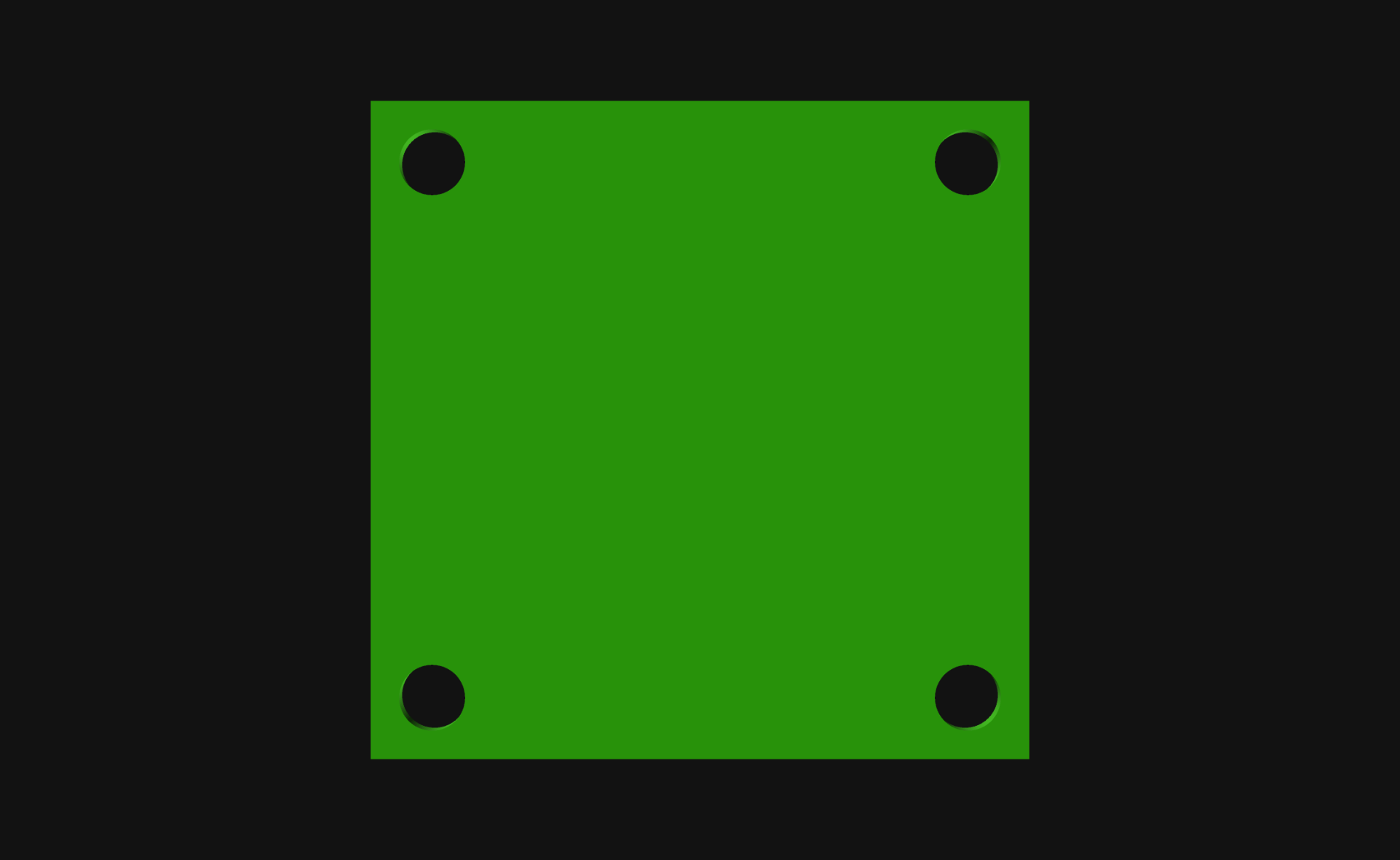
You can put the holes on a square instead… or a rectangle, or anything, really. And they don’t even need to be holes… I just needed holes for this specific example.

Another square with some holes…

And yet another square with some holes… This time with a different startAngle set.

Those holes look a little large… can we make them smaller?

We sure can! Look at that… Obviously you are not limited to just making circles, and this technique of using a for loop to put things around the center of an object can be expanded in many ways. I just wanted to share this recent remembrance so I can find it again when I need it!

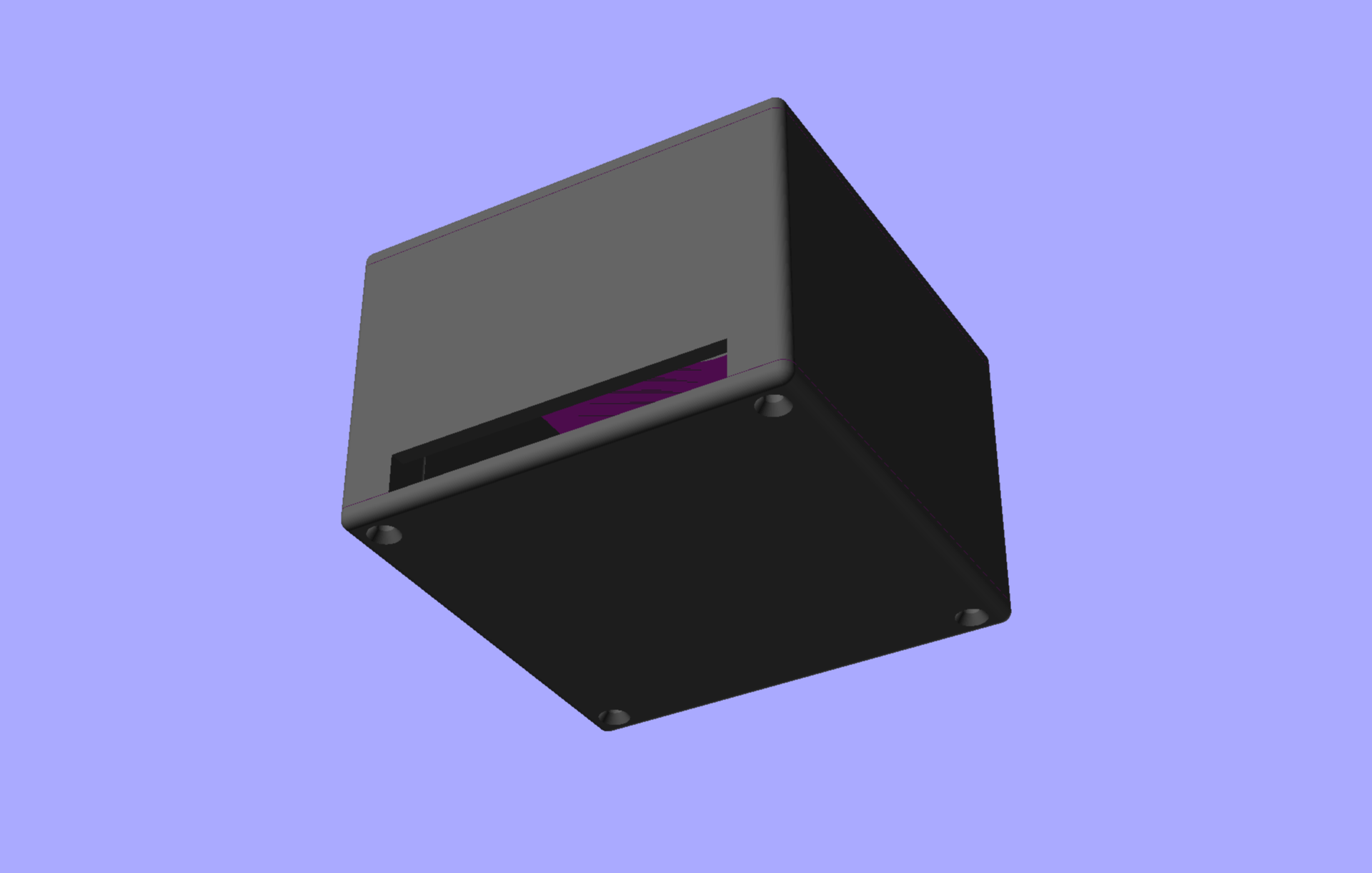
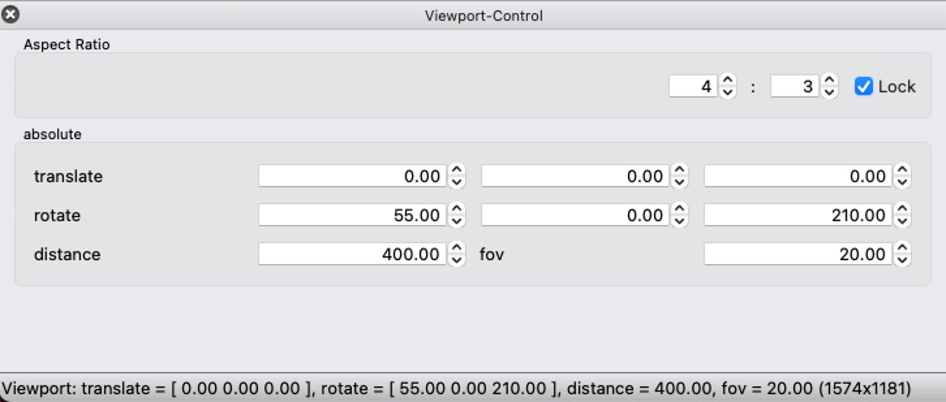
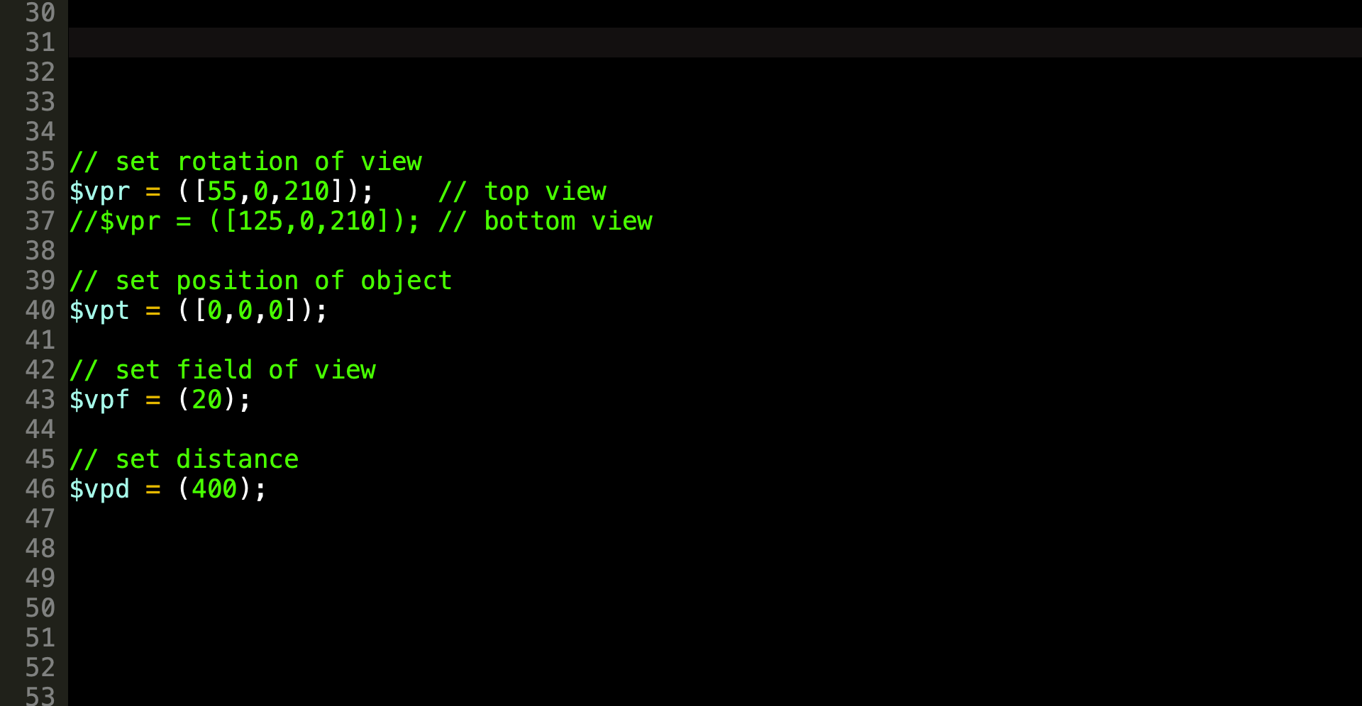
By the way, these OpenSCAD renders were all done using my Cyber Night theme for OpenSCAD.
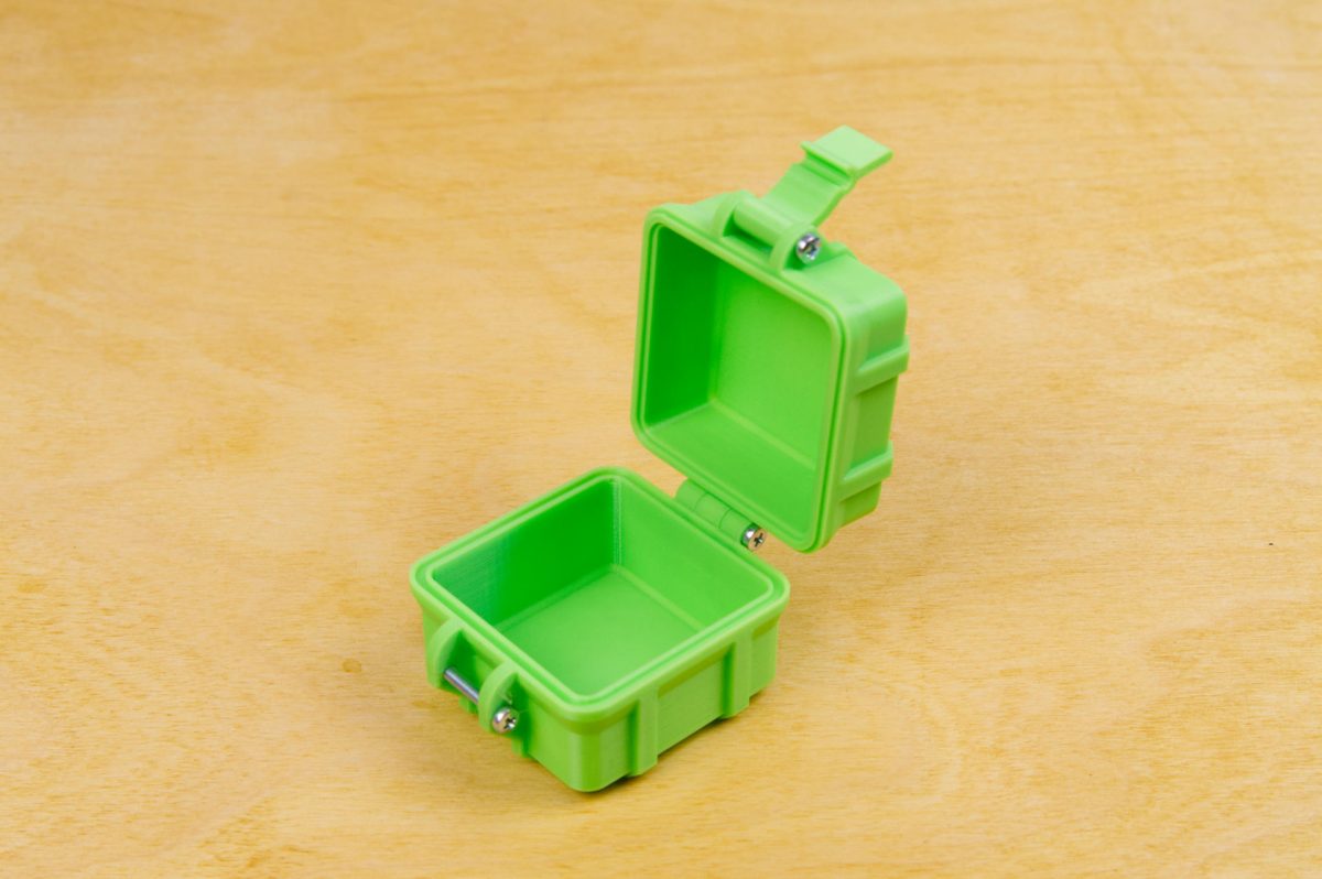
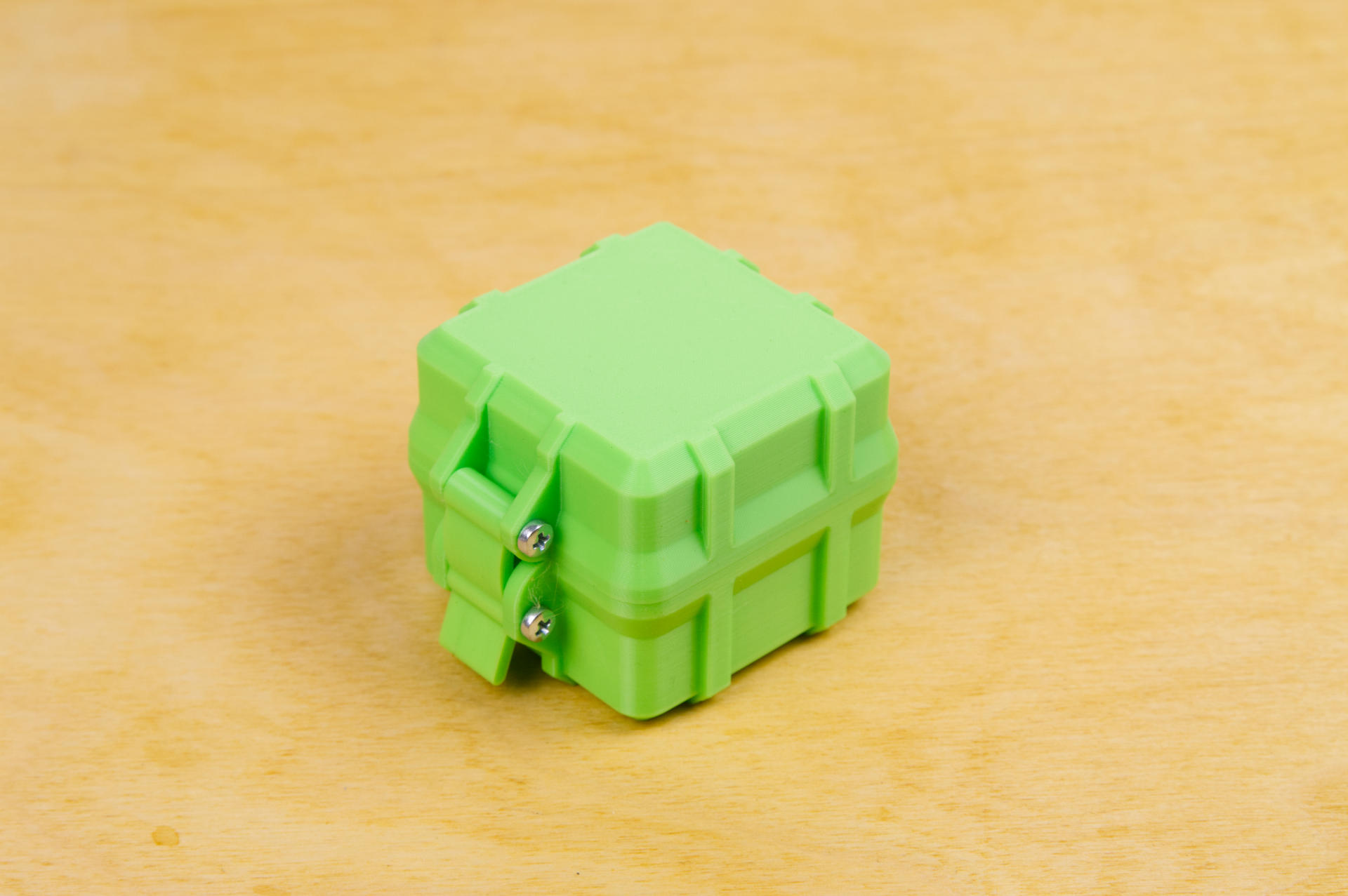
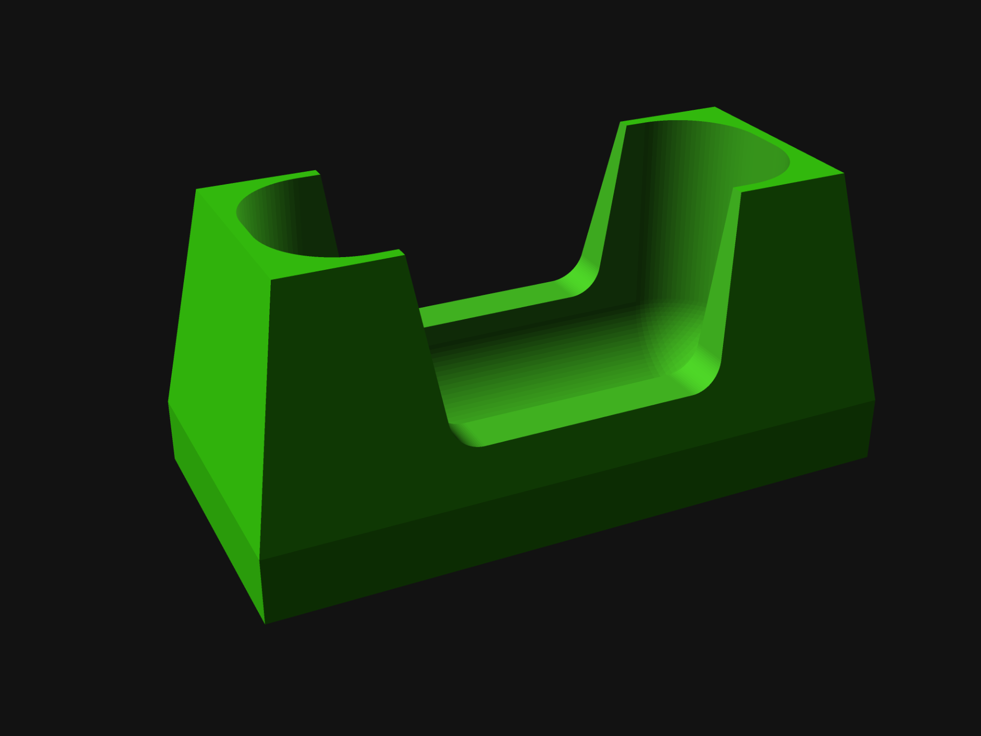
Categories
Uncategorized

A 3D Printed Pegboard

Pegboard! It’s the classic way to hang tools in a workshop. Is it the best way? Probably not. It is easy? Sort of. Are there better ways of doing things? Definitely. Anyway, I decided to move forward on this project for a few reasons.

My basement workshop has two large sections of pegboard and a mess of tools. I am in the process of organizing all of those tools, and along the way Kyle Davis was kind enough to mention something called Pegmixer, an OpenSCAD library he had created. I prefer OpenSCAD for my 3D modeling, and once I dug into the library it was much better than the other (quite old) customizable pegboard hanger things I was looking at.

But wait, why the “3D Printed Pegboard” part of this? While you can grab a (nearly) 4 foot by 2 foot pegboard from Lowes for $12 USD, or a nice looking fancy SKÅDIS 30×22″ pegboard from IKEA for more than twice that price, I wanted to try some large prints on the Bambu Lab P1S printer, with a build volume of (almost) 256x256x256mm.

So I grabbed a cheap roll of black Sunlu filament for $14.69 USD and with the help of the openscad-pegboard-peggrid library designed some pegboard.

Now my initial idea was to laser cut some pegboard using this library and all of the scrap 3mm plywood I can get from work, but that also seemed like a silly idea, and with 3mm thickness it would not be compatible with my existing pegboard which is much closer to 5.5mm. By 3D printing the pegboard it would allow me to match it up in thickness to what I already have, so I can move things between them.

I used Pegmixer to create a simple plate that could be used to align the pieces so the spacing of the holes was lined up across sections. Once I put one panel up I then used two plates to align the next one and then screw it into the wall using some drywall screws in the corner holes.

I also printed four spacers for each panel to offset them from the wall. Nothing fancy, just some cylinders with holes large enough for the screw to go through. I ended up gluing them to the back of the panels for ease of installation. I originally had them integrated into the panel but opted to just print them separately.

I know some people will question the logic of 3D printing a pegboard instead of buying one (and cutting it to size) or even laser cutting one. I covered some of the answer in my Printing versus… Not Printing? post. Sometimes cutting things with a saw isn’t easy, or isn’t possible, so printing can be a quieter and much less messy alternative. It can take longer, but it can also happen offline, meaning when you are at work or otherwise busy. For laser cutting a pegboard you need a bunch of flat stock, which (depending on size) may be more costly than a $15 roll of PLA filament. (I did manage to print six panels from one roll, though according to the math I could have got 8 total since each uses 118 grams of filament.)

And yes, I do know about the Honeycomb storage wall that seems to be all the rage, but I opted to stick with the system I already have going. Compatibility and all that.

The 3D printed version (printed face down on a textured plate also looks really nice. Standard pegboard does tend to look a bit ugly. Obviously you can paint it, or with laser cut wood you can stain it, or just buy the IKEA version, but again… it’s all about options. And sure, while it looks good, it is in the most terrible looking room in the house, located in the basement… but I’ve considered adding one to my office as well, where a nice looking pegboard would be more appreciated.

So in the end, I’m really pleased with the look (and functionality) of the new pegboard, and now I need to get back to designing all the things that will attach to it to hold tools and other things!

If (for some reason) you want to use the exact same files I did, you can get the STL and .scad files from Printables.com – Pegboard Panel . Otherwise just grab the library, apply a fix if needed, and do your own thing.

Categories
Uncategorized

NIIMBOT D11 Stand

I recently grabbed a NIIMBOT D11 thermal label printer, which is a small/portable device for printing labels. It works well enough (I’m working on a full review for another post) but one of the things that annoyed me is that it cannot stand upright on a desk

For some reason the designers decided that a rounded bottom would be fine, and so it you can lay it down, you can stand it upside down, but you cannot stand it upright, so I fixed that.

This design took a few iterations, and I ended up adding the cutout to use less material, and (hopefully) allow for printing in less time.

This is one of those things I really thought would exist already, but a cursory search yielded no results. So here it is.

As usual, the OpenSCAD file is included if you want to make changes. The BOSL2 library is needed, and this is the first real project I’ve used it on, but it will not be the last.

You can get the STL and .scad file from Printables.com – NIIMBOT D11 Stand. Print it if you need it!