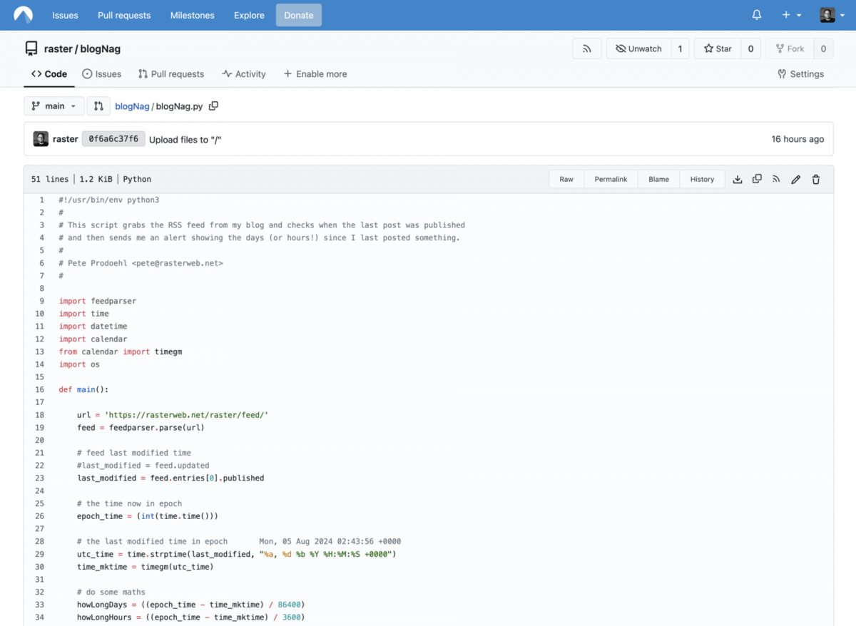
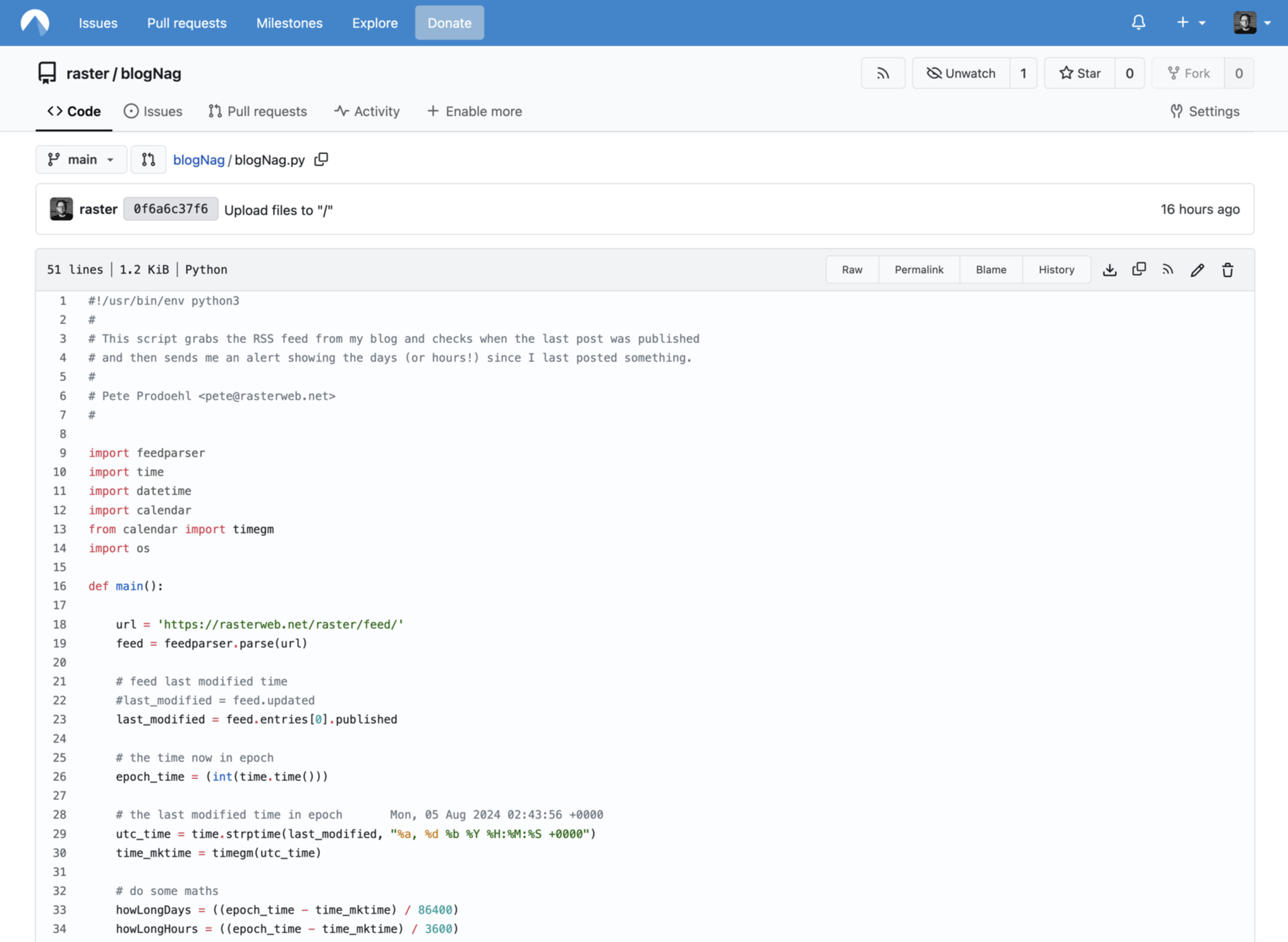
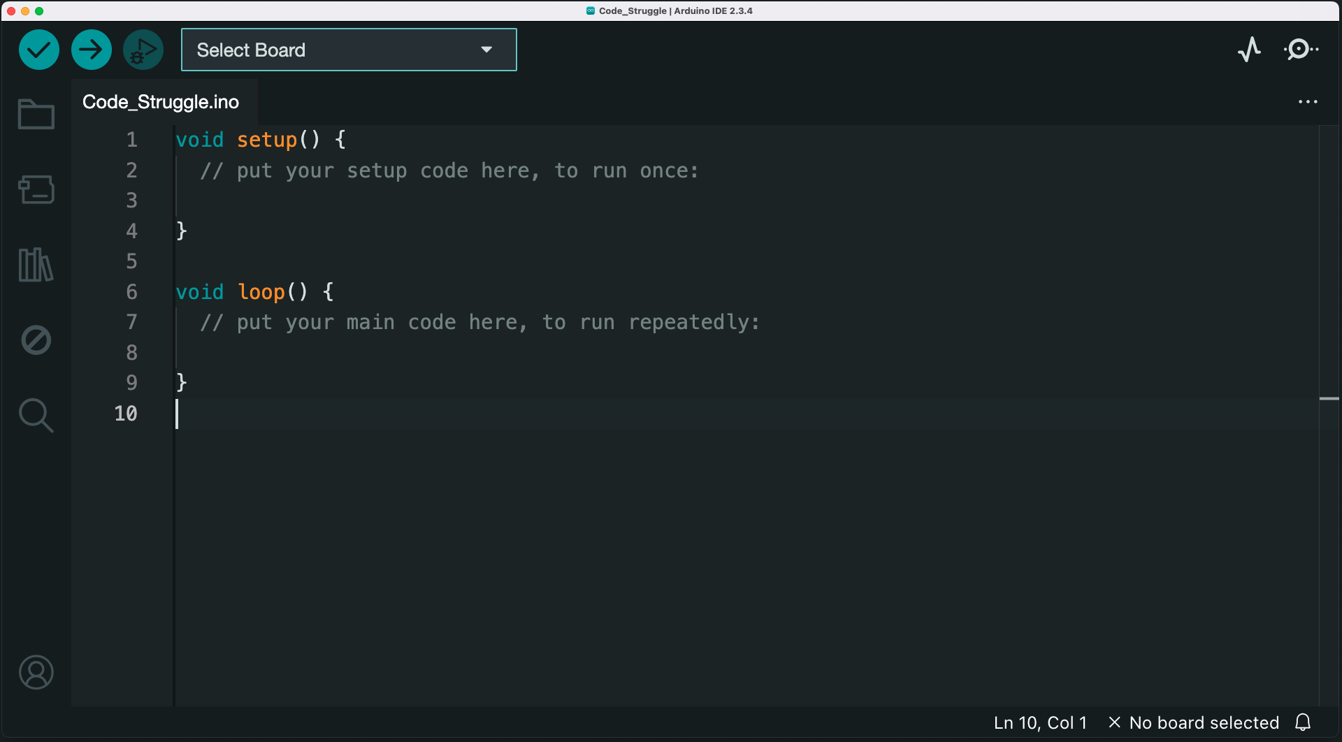
I will start with the disclaimer that I’ve never held the title of “Software Developer” or even “Programmer” and my career has been built on being a “Hacker with Many Hats” kind of person. So I tend to go broad and not go deep on a lot of things. I’ll confess, I’ve used a fair amount of global variables in my code, probably some where I should not have. As an old-timer Perl Hacker, it’s… meh. My code was often quick & dirty to get the job done, not elegant and meant to last.
That said, even though I read an entire book on OpenSCAD I somehow had it in my mind that variables in OpenSCAD could not be changed during run-time, as it were. OpenSCAD is… weird, but I’m okay with that. Supposedly variables in OpenSCAD should be thought of as “override-able constants” rather than as variables in the traditional sense.
Or you can look at my example above… Because yes, you can change the value of a variable in a function / module! Variables are local within a module!
Here’s the demo code shown above. I am guessing 98% of software developers are saying “Duh!” right now… so this post is for me, and people like me, who may have missed this, may have been confused by this, or just needed a simple demo.
When writing code for yourself you can choose to leave it messy and confusing (though you may not want to) and when writing code that other people will see it may be a good idea to attempt to be clear and organized. I’m trying to be more clear an organized. Which you know, can help your Future Self as well.
Here’s a recent project. It’s a 3D model of a simple foot switch. There are two 3D printed parts (a base and a cover) and one non-printed part (a push button) and sometimes I want to see one part, and sometimes I want to see all of the parts together.
Another thing I’m hoping this helps with is that since you need to export each part individually for slicing and printing I used to just add a line that said “Uncomment this to export” above each item to be exported.
I figure this is a bit cleaner as you just need to toggle some values between 0 and 1. (And yes, you can do an export that is all parts laid out ready to print but I tend to not do that.)
Anyway, I’ve never really read up on best practices for writing OpenSCAD code. I’ve picked up things over the years from looking at code others have written, and from making my own mistakes and wanting to improve them.
If you know of any good tricks or have some tips, let me know!
Update: Someone asked why I was using 0 and 1 instead of false and true. I am not an expert on this but I believe since OpenSCAD is not strongly typed that 0 and 1 pretty much work as Boolean values and the only real difference is readability. If so, it’s really just a personal choice. (Let me know if that is incorrect.)
In the interest of not waiting too long after I build something to share it here, I’m going to drop a bunch of random info into this post, knowing that it may not be well written or cohesive, but I’ve decided that’s okay…
Logo is an educational programming language known for its use of turtle graphics. Commands for movement produce drawings on a screen that teach students to understand, predict and think about the turtle’s motion by imagining what they would do if they were the turtle.
And finally, if you’re not familiar with Brinn Labs (where this was created) we are were the exhibit development group of a children’s museum, and we make made safe, durable, fun, educational exhibits for museums and other institutions, mostly aimed at early learners.
Here’s the original concept I shared with the team. Things always change during the development process, but this is still pretty close to what we came up with.
In designing the physical board and pieces, I took inspiration from the block interface used by Scratch. In Scratch pieces fit together to help you figure out where things go, and color also help denote function.
Here’s a mock-up of the board where the pieces will go. The board has pockets that the pieces fit into, and in each pocket is a sensor that reads the back of the piece. Note that the pieces only fit into the pocket that matches the function. You can’t put a direction piece into the color pocket. The pieces also cannot fit in backwards or be rotated in the wrong direction. Designing this to work took some time, and it’s all there to help you get it right.
The right side shows the indent for the loop code, as well as the use of parens that many programming languages use. Note that the loop pieces are not required, but if you put in the beginning loop statement and not the end loop statement (or vice versa) you’ll get an error.
We’re using the QTR-8RC Reflectance Sensor Array boards from Pololu. Each pocket has one sensor board to read the barcode on the back of the pieces. The barcode allows us to use a binary code for each piece. This means no technology is embedded into the pieces, and they’re (fairly) cheap and easy to replace as needed.
Here’s a look at the print file for some of the pieces, showing the back. You can also (faintly) see the cut lines for the pieces.
Here’s a portion of the binary code for some of the pieces. We actually doubled it up as a sort of checksum to make sure things were read right.
Each sensor is mounted from the back of the panel with a 3D printed mount that sets it right below the surface. We found a gray filament that was a pretty close match to the gray HDPE we used for the front panel. The top part of the sensor mount matches the holes milled into the HDPE by the CNC router, and includes the radius of a 1/4″ router bit.
My favorite part about 3D printing the sensor mounts is that you can set the height of the part where the screws go to match the screws you use and the material you are screwing into so they go in the exact distance you want, and not too far. No screws poking through material, and no screws not inserted enough to get a good hold.
We couldn’t leave the sensors exposed, so we laser cut clear acrylic pieces to place into the pockets. Hopefully they’ll stand up to the abuse they’ll get, but if they get too scratched or worn, it’s easy to swap in a new one. (If you’re keep track, we’ve used a 3D printer, laser cutter, and CNC machine so far…)
Here’s a look at a mock-up of the pieces. This is an early iteration but shows some of the color choices as well as all the pieces together.
I’m not showing you the inside of the cabinet, but all of the sensors connect to a microcontroller that is connected to a computer. The microcontroller reads the sensors, determines which pieces are in which pockets, and reads the button presses to run the code on the computer and reset things.
To program the turtle, you put the pieces in the tray, and press “Run”. If you get an error it will show on screen and also blink an LED on the board for the “line” where the error is. Once you correct your error(s) you can hit “Run” again and watch your code execute. You can run over and over until you want to clear the screen by pressing the “Reset” button, which clears things and sends the turtle back home.
We didn’t implement pen up/pen down, because this is a simplified version meant for young children/early learners. I think that as far as a STEM component it turned out well, and creating it allowed me to combine my love of computers, programming, turtles, Logo, and design into something awesome.
I hope Seymour Papert would be proud of this. If you’re not familiar with his work, he’s been considered the world’s foremost expert on how technology can provide new ways to learn and teach mathematics, thinking in general, and other subjects.
People laughed at Seymour Papert in the 1960s, more than half a century ago, when he vividly talked about children using computers as instruments for learning and for enhancing creativity, innovation, and “concretizing” computational thinking.
Here’s some kids having a good time learning about coding!
One of my PCOMP students wants to randomly select a set of RGB values from a predetermined list. It’s the sort of things where I know the concept is easy but the execution is a bit more difficult only because I’ve done it in other languages/environments, but not in an Arduino sketch.
The nice thing about programming is that once you know how to do something using one language, the concepts transfer over to other languages, and it becomes mostly a matter of figuring out the syntax and method to make it all work.
Here’s an example sketch that allows you to have a list (array) of RGB values and then randomly select one and return it, split the r, g, b into their own integer variables, and then print them to the serial monitor. (The final version will use analogWrite to control RGB LEDs.)
Update: Royce has his own version you can check out. He suggests it should be more efficient because the textual RGB values are converted to binary at compile time rather than runtime.
I saw many friends share this amusing image of a fake O’Reilly book titled “Copying and Pasting from Stack Overflow”, and if you’re not in on the joke, Stack Overflow is a web site where you can post programming questions and get answers to those questions. It’s also a site (like many others) where people who are not sure what they are doing grab bits of code from when they are not 100% sure what they are doing. (And if you don’t know about O’Reilly, they publish technical books, many about programming.)
This is the first semester I’ve taught a class that includes programming. I was upfront with students about how I’ve learned to write code over the years, and that includes looking at examples, using existing code, and (eventually) reusing my own code. I didn’t force them to type out each line of an Arduino sketch because I didn’t think it was completely necessary. They already know how to type, and once I showed them how to hit the compile button, they learned about syntax errors. Occasionally in class I’d demo things by writing code on the fly and inviting them to type up what I just typed, and to play around with the values, add more lines, etc. (I showed them the “Examples” menu early on, which contains plenty of useful code to get started with.)
Here’s something that may be news to some readers – I’m not a great programmer. I’m a hacker, and I can write enough code to get by, but more importantly I can find enough sample code and examples and tutorials to write the code that I need to do what I want to do. I think that’s the key to things.
If you’ve ever heard the expression “To be a great writer, you need to be a great reader” then perhaps this also applies to programming, and reading code is an important part of writing code.
Now, with all that said, I still expect students to learn some of the basics of writing code and understanding it. If at the end of the semester all they’ve done is copied & pasted code that someone else wrote, and by some miracle it compiles and runs and works for their project, that’s still sort of good, but not quite as good as having a basic understanding of what exactly those lines of code are doing.
In the meantime, keep copying code, and pasting code, and while you’re at it, try to read it and understand it.