![]()
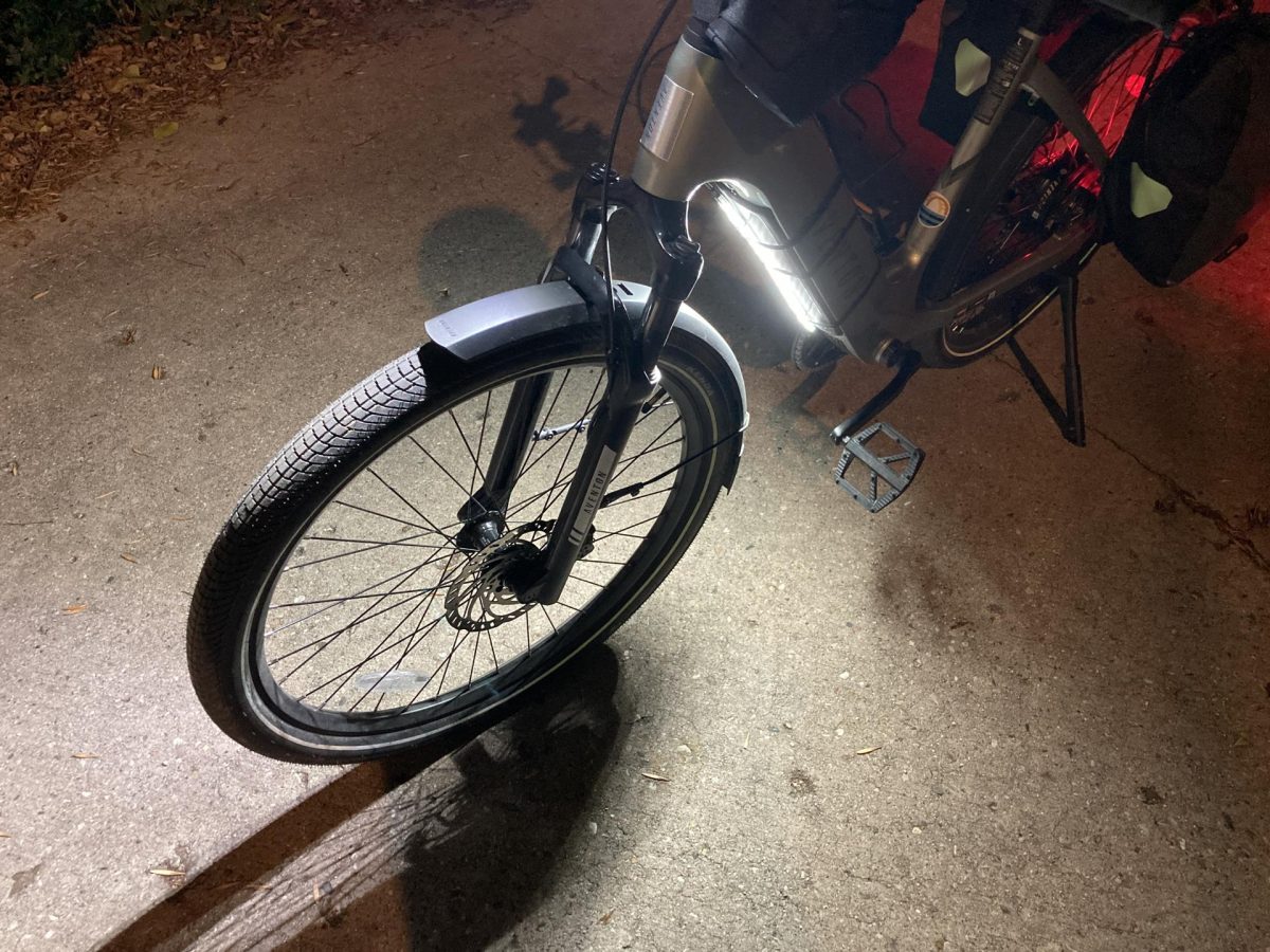
About a month ago I posted about my first NeoPixel Bike Light but I’ve also been working on a newer version, and also got distracted along the way, but came up with a compact version, well, two versions. Here’s the first one.
![]()
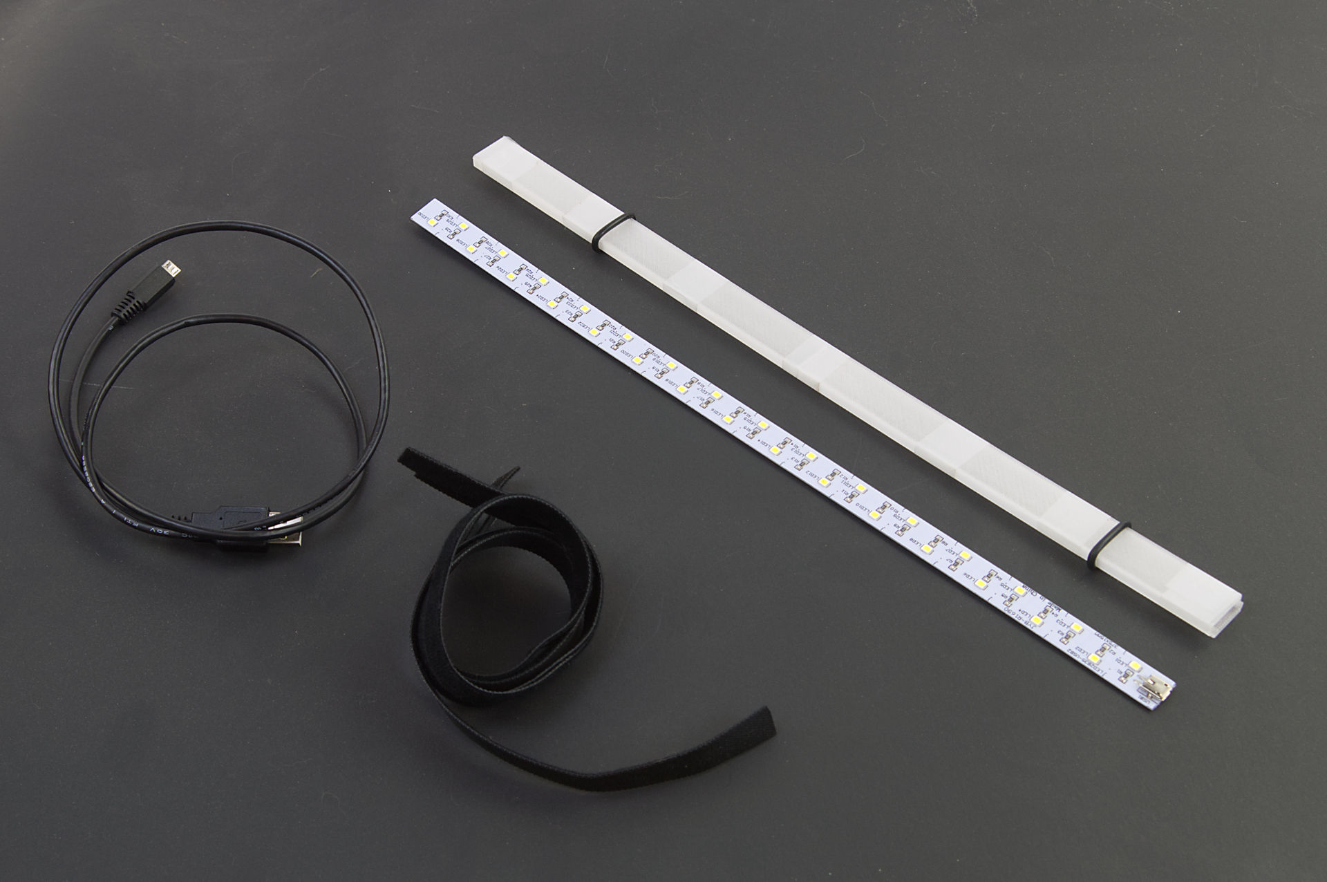
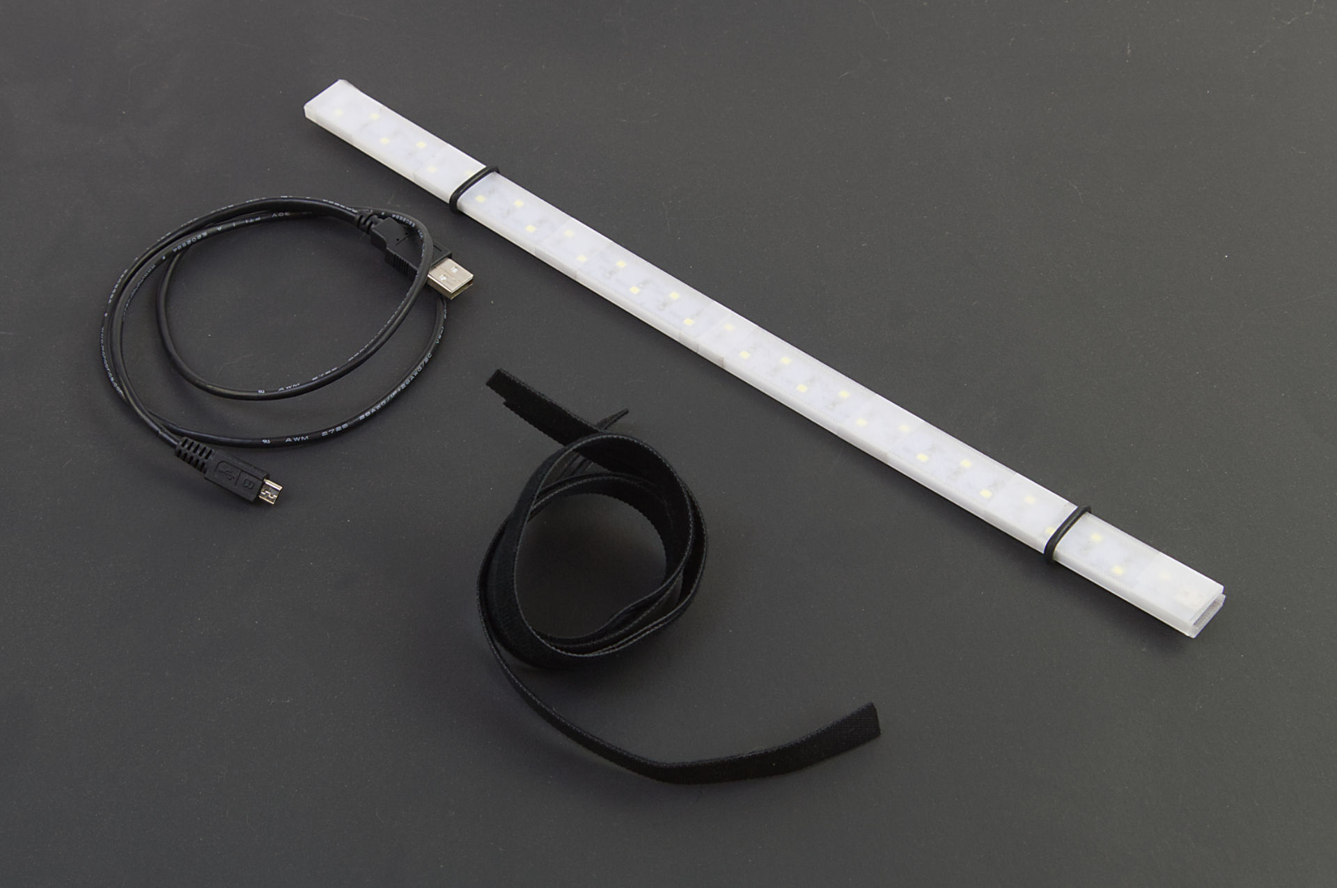
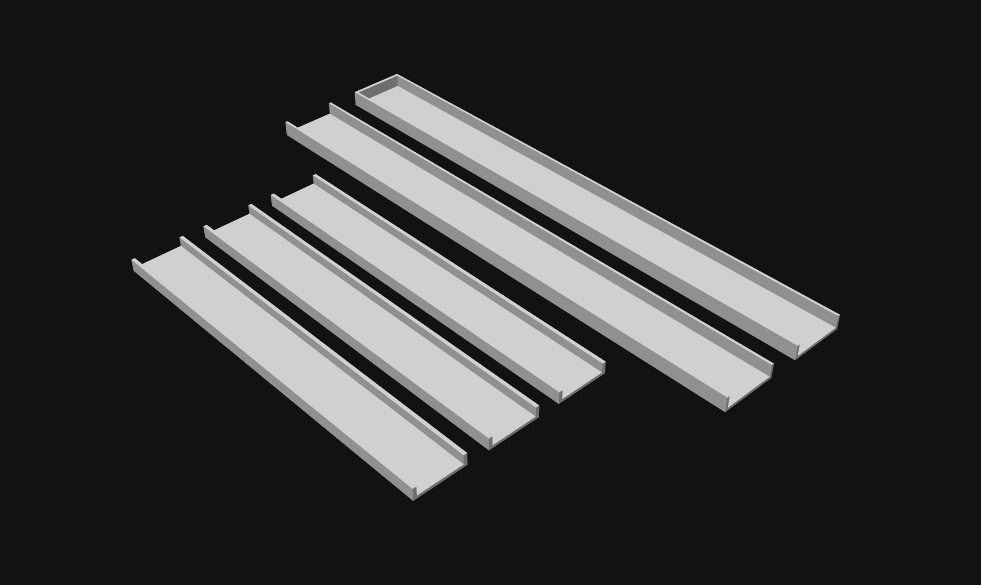
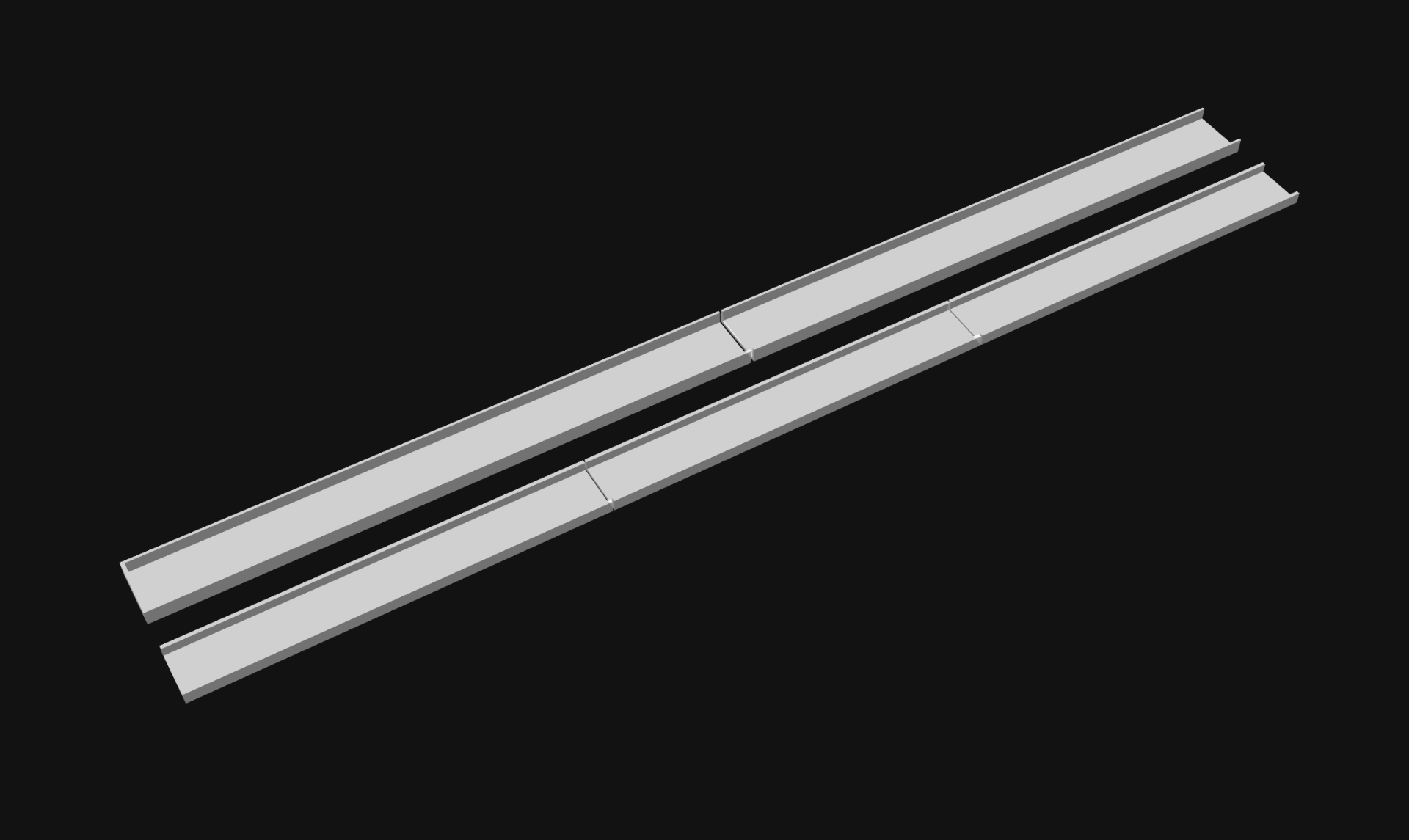
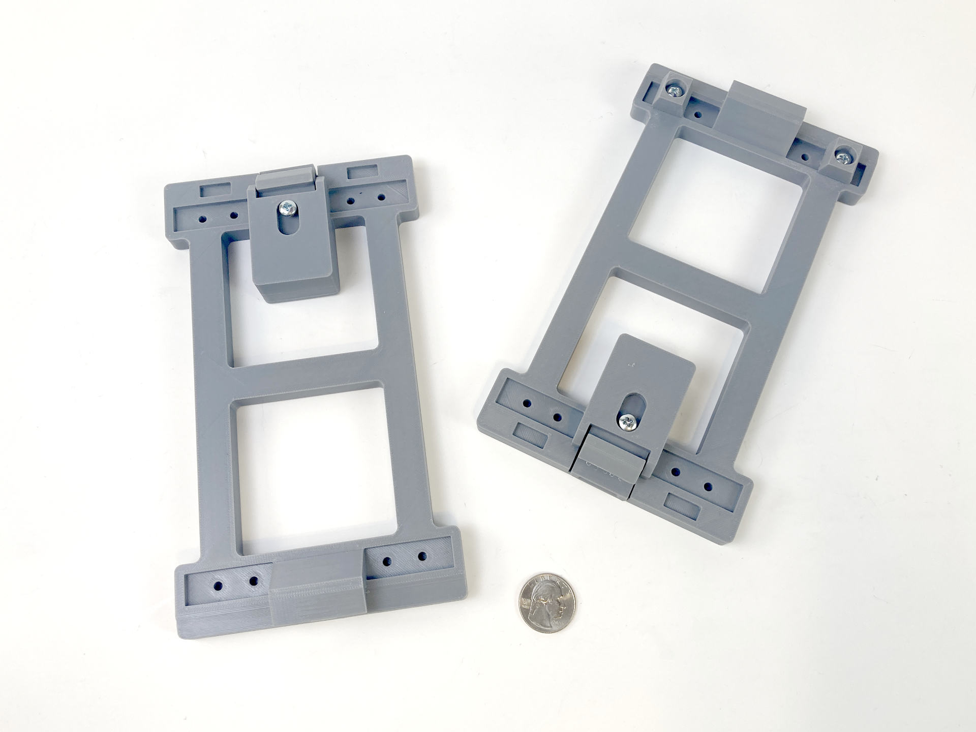
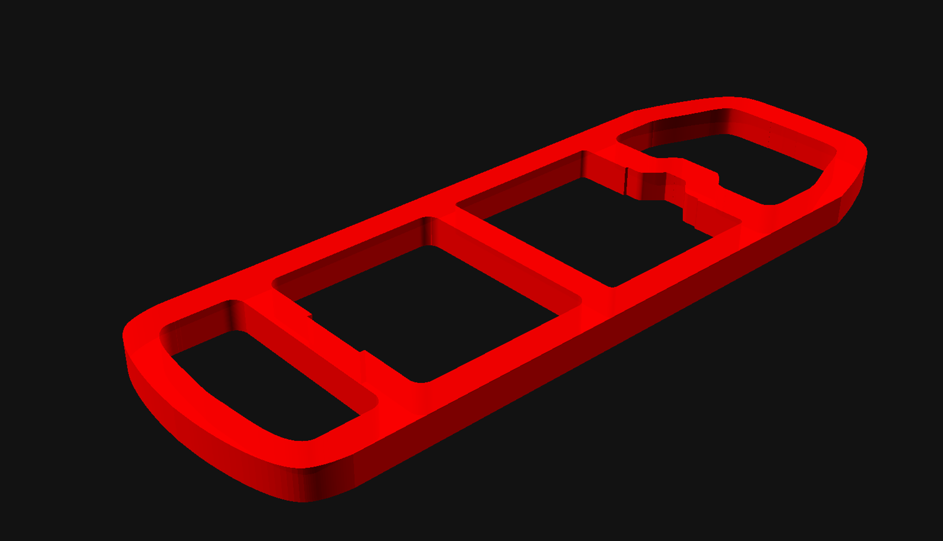
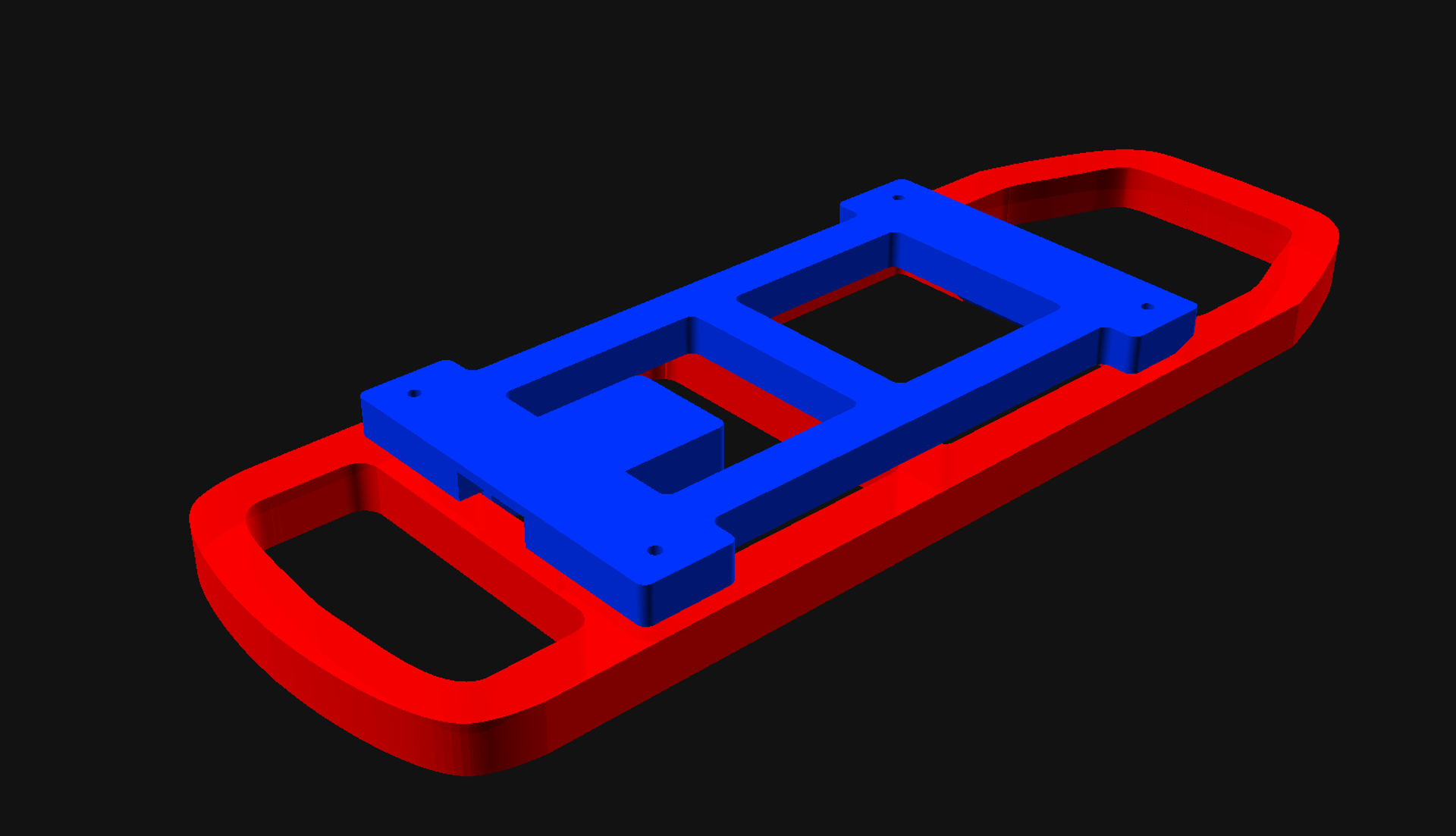
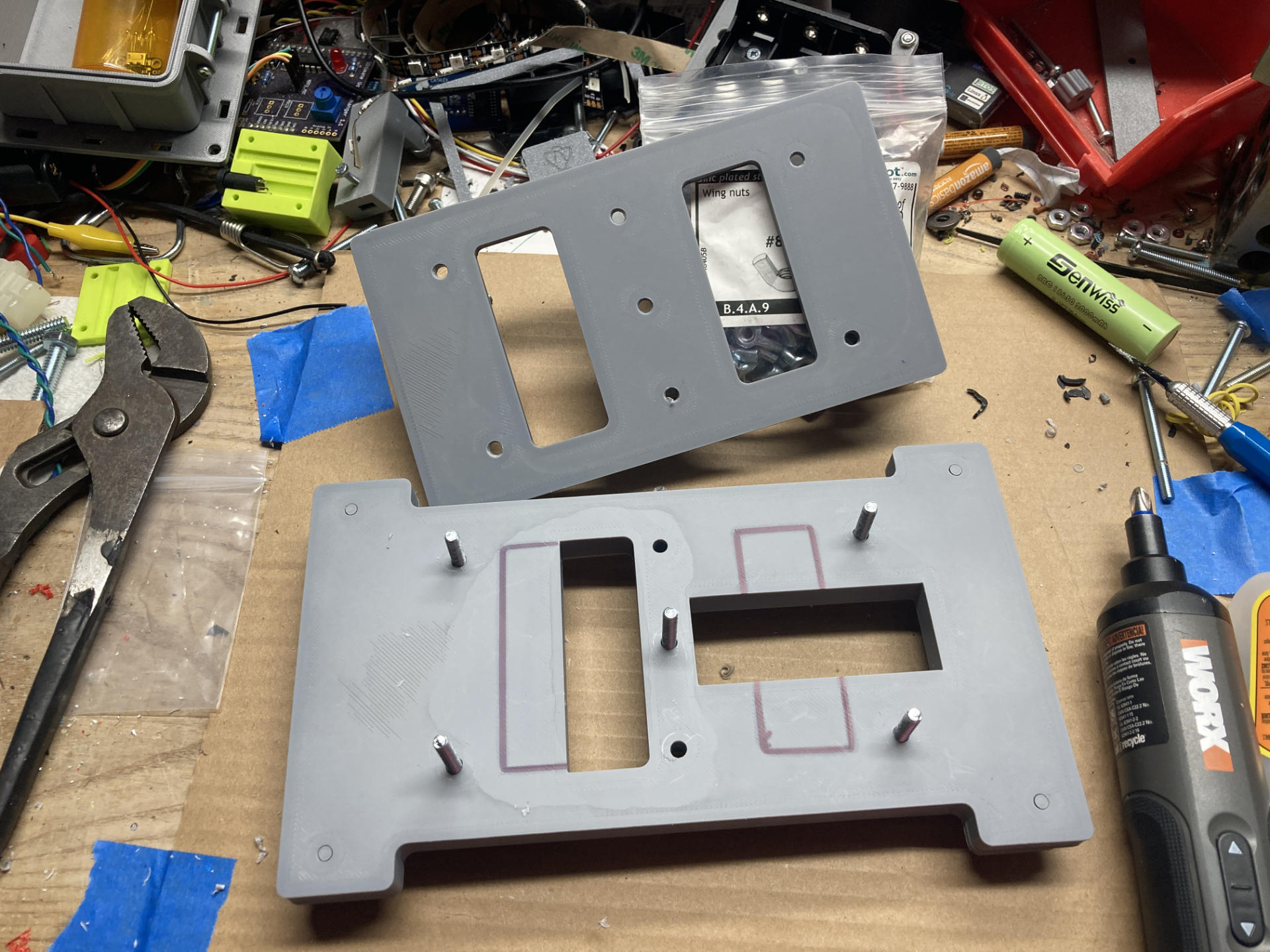
I designed five parts that were then 3D printed, and added in a thin sheet of 0.04″ thick PET plastic.
![]()
It’s all held together with four button head screws in the corners. This back cover is plain (and white!) but I have something else in store for an upgrade coming soon.
![]()
There are two Micro USB ports on the side, one for charging and one for programming. I don’t love that they are exposed so that’s something I’ll work on in a future version.
![]()
Let’s look inside! There’s a 8×8 NeoPixel panel, a microcontroller, a charge controller, and a lithium battery. Here are the parts:
- MakerHawk 3.7V 1000mAh LiPo Battery
- MakerFocus TP4056 Charging Module
- 8×8 WS2812 LED Matrix
- Raspberry Pi Pico
- Mini Rocker Switch
- Schottky Diode
Let’s talk about the parts!
I never really build electronic things that use LiPo batteries and chargers, so this is somewhat new to me. For this project the LED panel sort of sets the X and Y dimensions, so I chose a battery that would be smaller than the panel. The batteries were a 4-pack but ended up being less than $5 USD each. The TP4056 Charging Modules come out to less than $0.75 USD each. They may not be the best, but they work. (Don’t forget to add a diode, though!) The ones I got were Micro USB but there are also USB-C versions. That’s our power sorted… oh, add a switch to make it a real project!
The LED Matrix comes in a two-pack for $11 so it’s about $5.50 for one. It’s a nice panel, seems to work well, and you only need to solder three wires to it. The mounting holes are in the middle of the PCB, not on the corners, which is fine. I just made pegs in my 3D printed part that it can snap onto.
Now, that Pi Pico. There are obviously smaller boards. I do prefer an RP2040 board nowadays if I can use one, and I usually have a few dozen Pi Pico boards in the shop. Alternately if you did want really small and maybe USB-C the Seeeduino XIAO 2040 would work great, though they often cost a lot more than a $4 USD Pi Pico. (Depending on where and how you get them.)
The The Waveshare RP2040-Zero is another small and cheap option. There are a ton of knock-off clones of that board under $4 USD each, but Waveshare is a good company worth supporting.
![]()
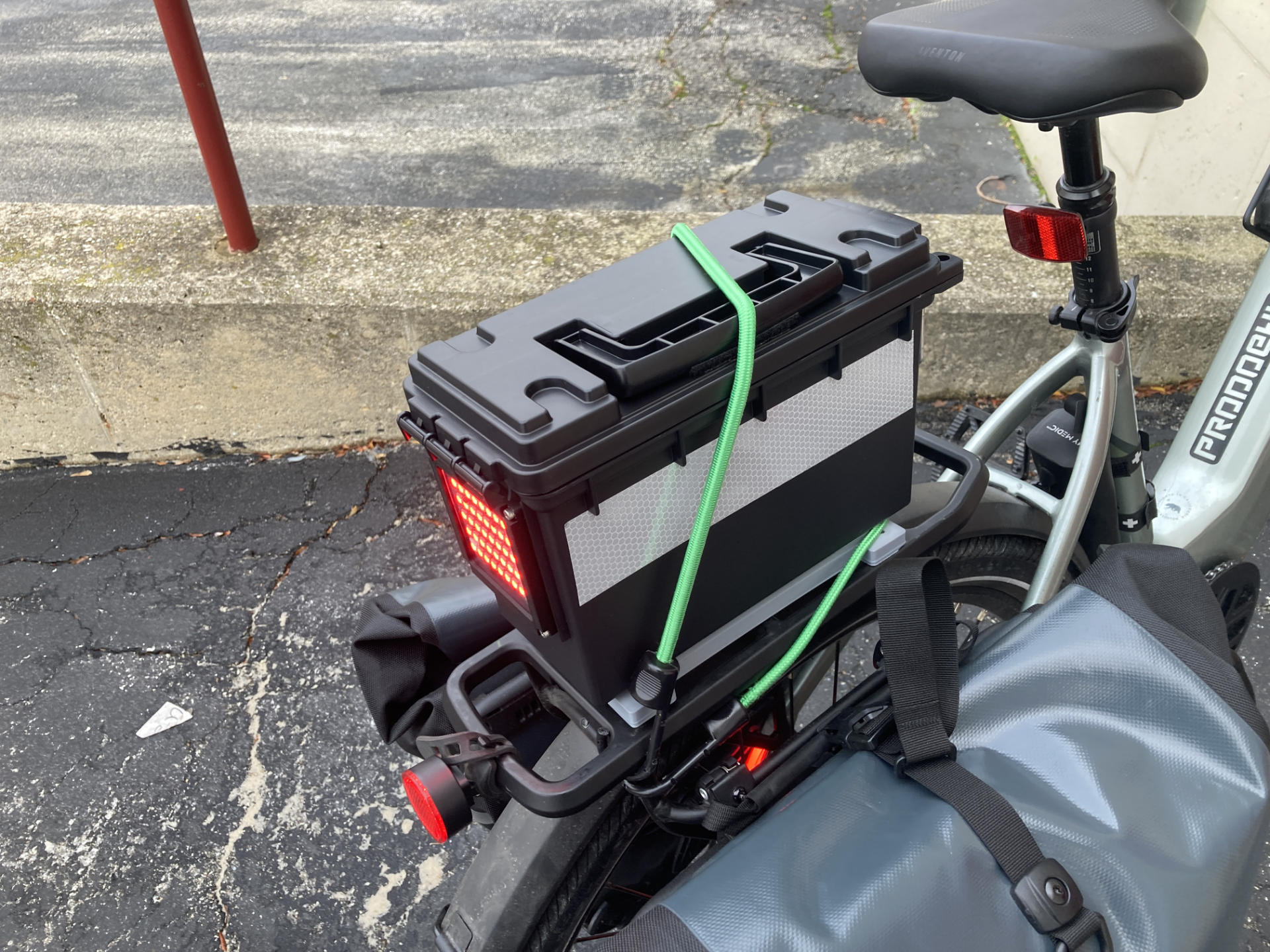
Hey, it lights up! You can program patterns or whatever. This one just does a “lime” color for reasons.
![]()
It’s fairly compact. I could make it slightly smaller (in fact, that’s in progress right now!)
![]()
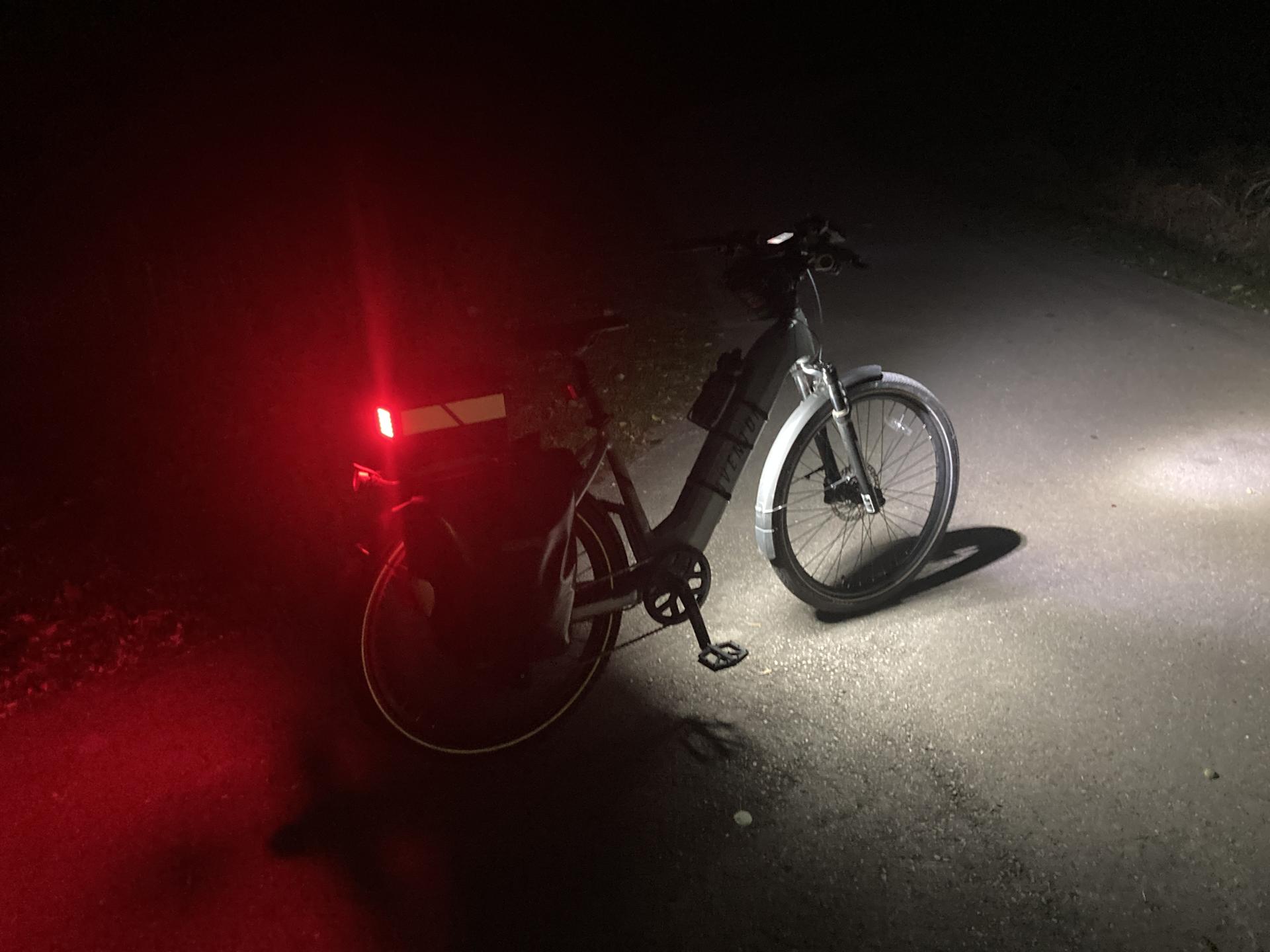
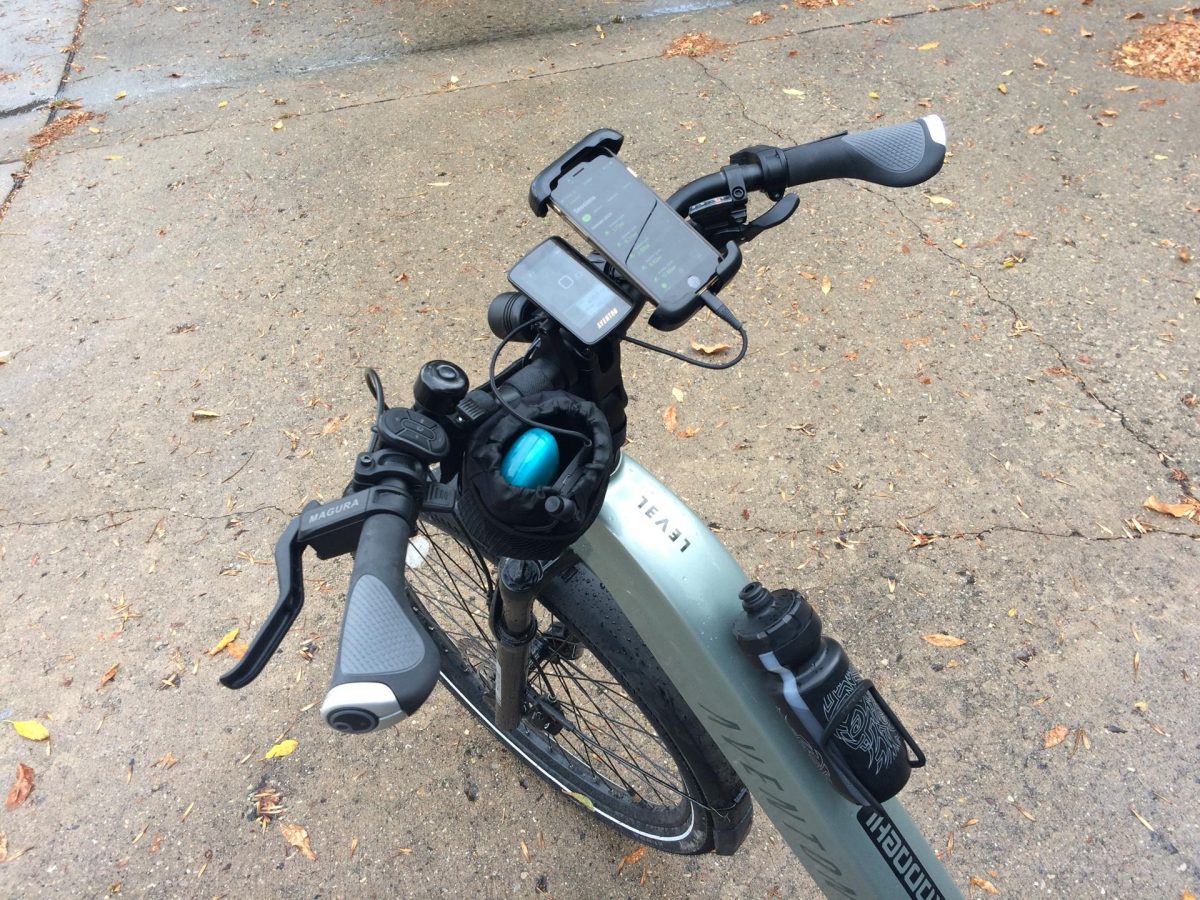
So this is what I call “Pocket Light 1.0” which is an old Adafruit Circuit Playground. I got two of the “Classic” or “Developer Edition” board a long time ago, I think for super cheap. Anyway, they have built-in NeoPixels, can be programmed, and run with an attached LiPo battery. I was dropping this into the pocket of my hi-vis vest for a little extra light when riding my bike in the dark of winter.
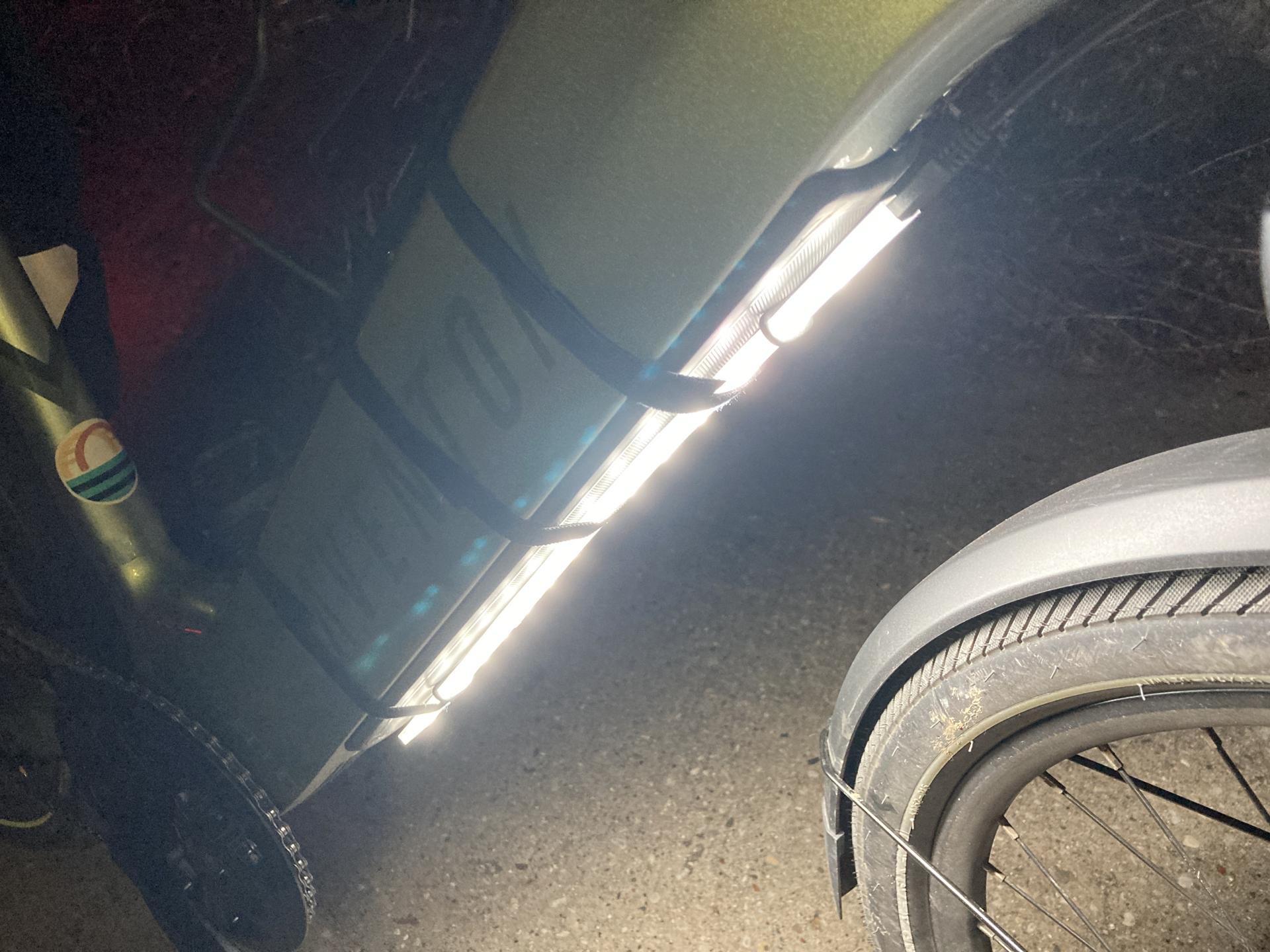
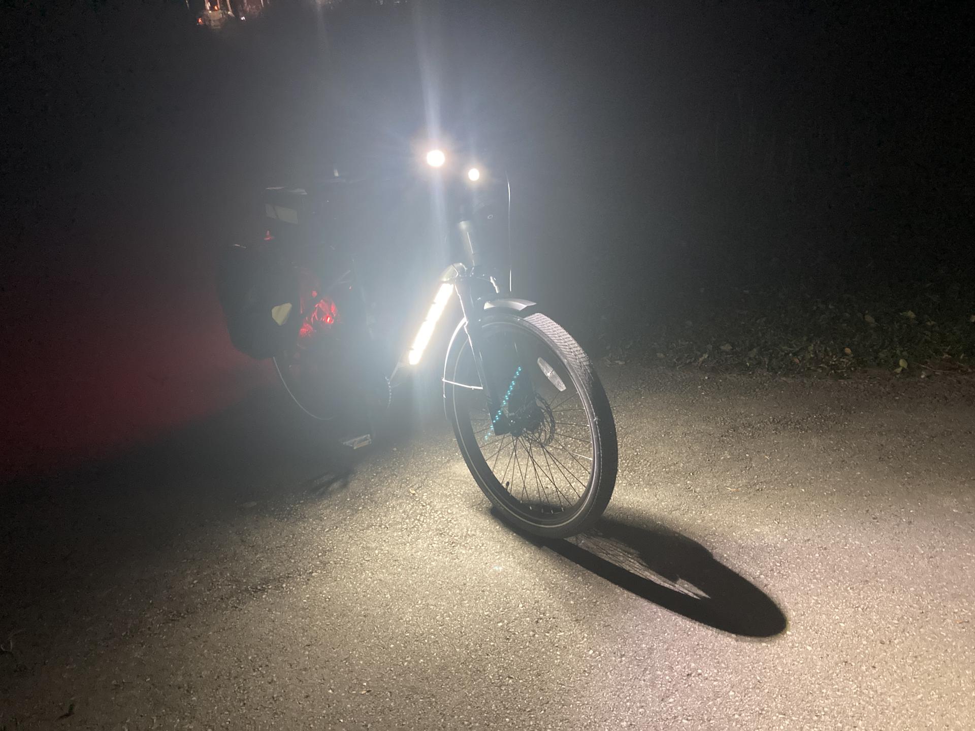
![]()
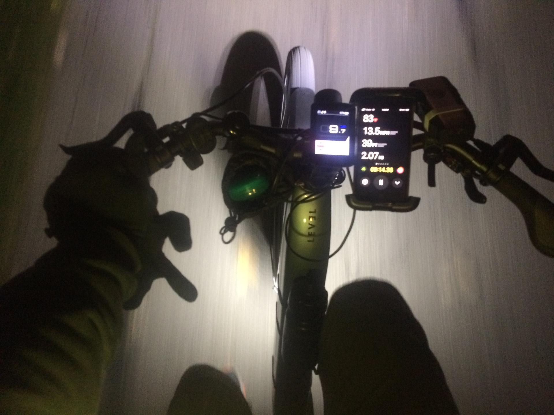
So here’s the light! In my pocket, shining bright. I’m mostly pleased with how it turned out, but also know there are improvements to make, and I can do better, so I will.
This post was too long, but I have more so I’ll expand on things in another post.
Note: This post may contain Affiliate Links. Read More.