Categories
Uncategorized

Fusing 3D Printer Filament

I’ve know about fusing the ends of filament together for at least a decade, but never really tried doing it. Until recently… I tried a few different methods, I did a bunch of reading, watched some videos, and I failed at nearly all of the attempts, or just wasn’t satisfied with the results. But somehow along the way I absorbed enough information to try something, and hey… it worked!

Note: Just want the files? Get them from Printables.

I read a lot of posts, and watched a lot of videos, and I feel that it’s sort of like 3D printing itself – what works for one person may not work for another – so find what works for you and go with that.

The method that is closest to what I did can be found on the Filament Splicer & Joiner with Roll Holder page. Rather than go through all the trouble of printing those parts and assembling it all, I took a simpler approach and went minimal to test things out.

The Tube
I ended up using this PTFE Tube (which is 1.775mm~ ID / 2.5mm OD). Wait, why is this important!? Most PTFE tube used in 3D printers (to feed filament to the machine) is 2.0mm ID / 4.0mm OD. Many methods use this size tube, and the issue is that the filament expands to 2mm inside the tube. The recommendation is to then shave and/or sand down the filament to get it back down to 1.75mm. This method constrains the filament to a dimension much closer to 1.75mm.

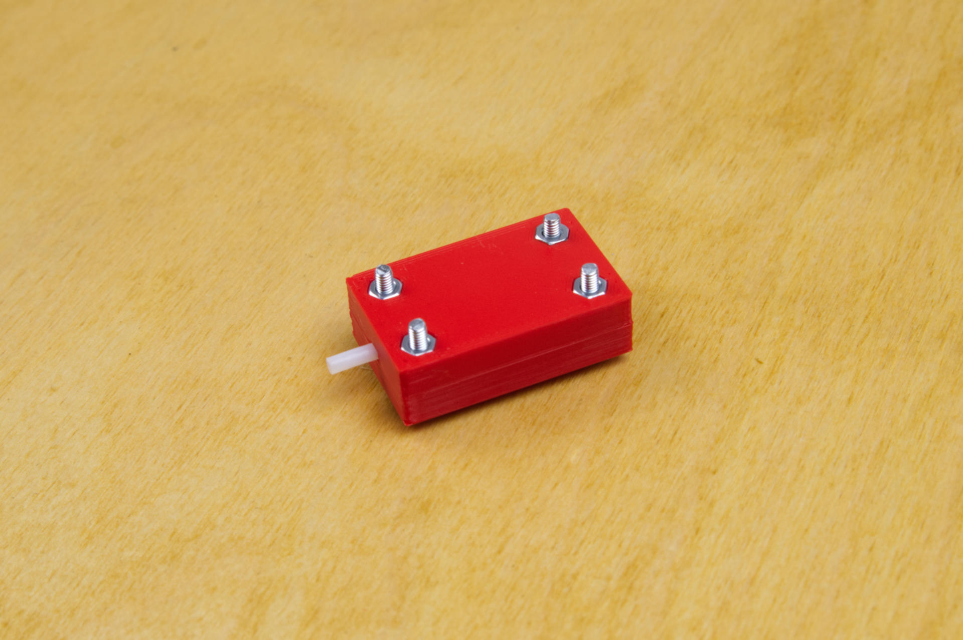
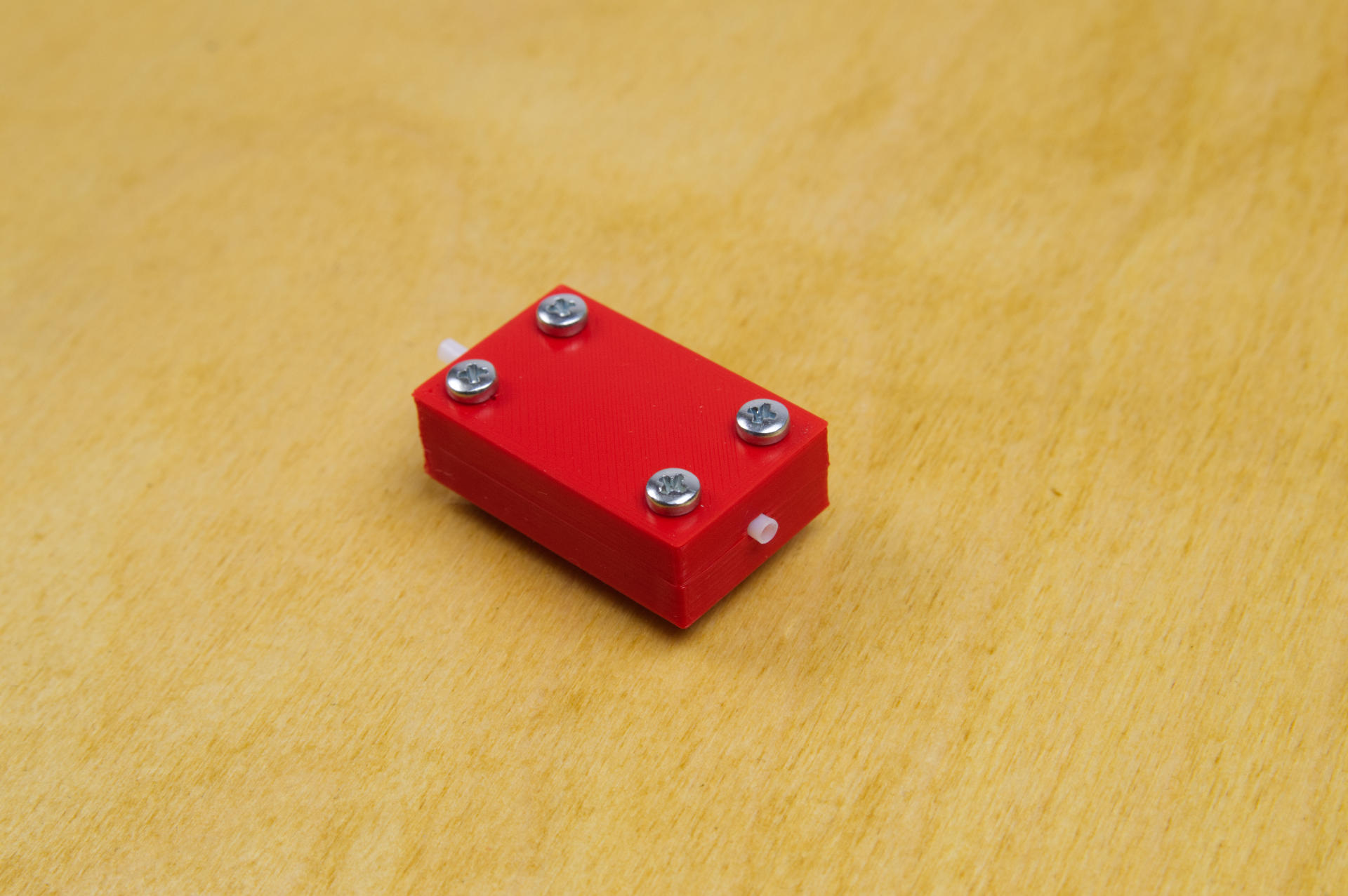
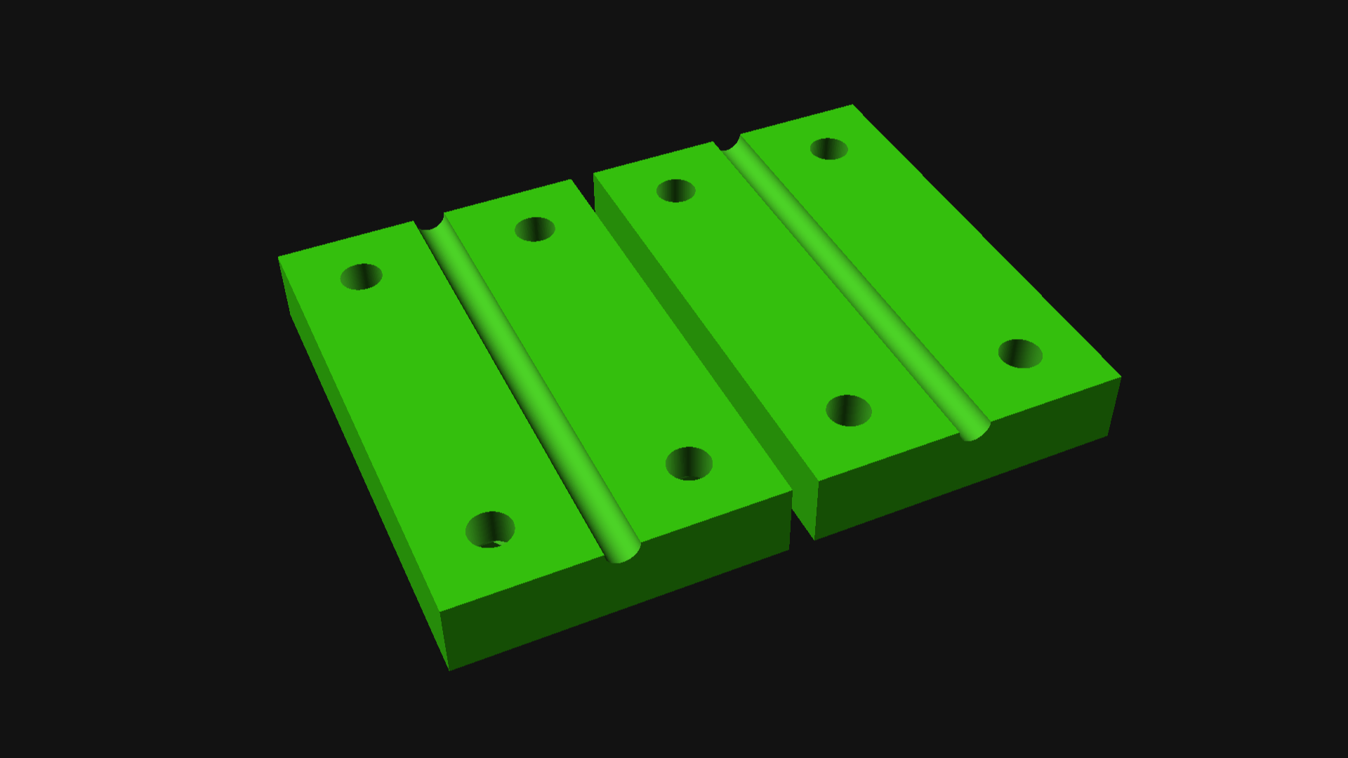
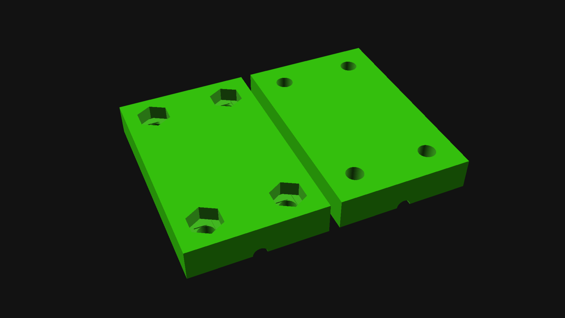
Besides the tube (which is the most crucial part of this whole thing) I designed and printed two parts and added a few 3mm bolts and nuts to hold it all together.

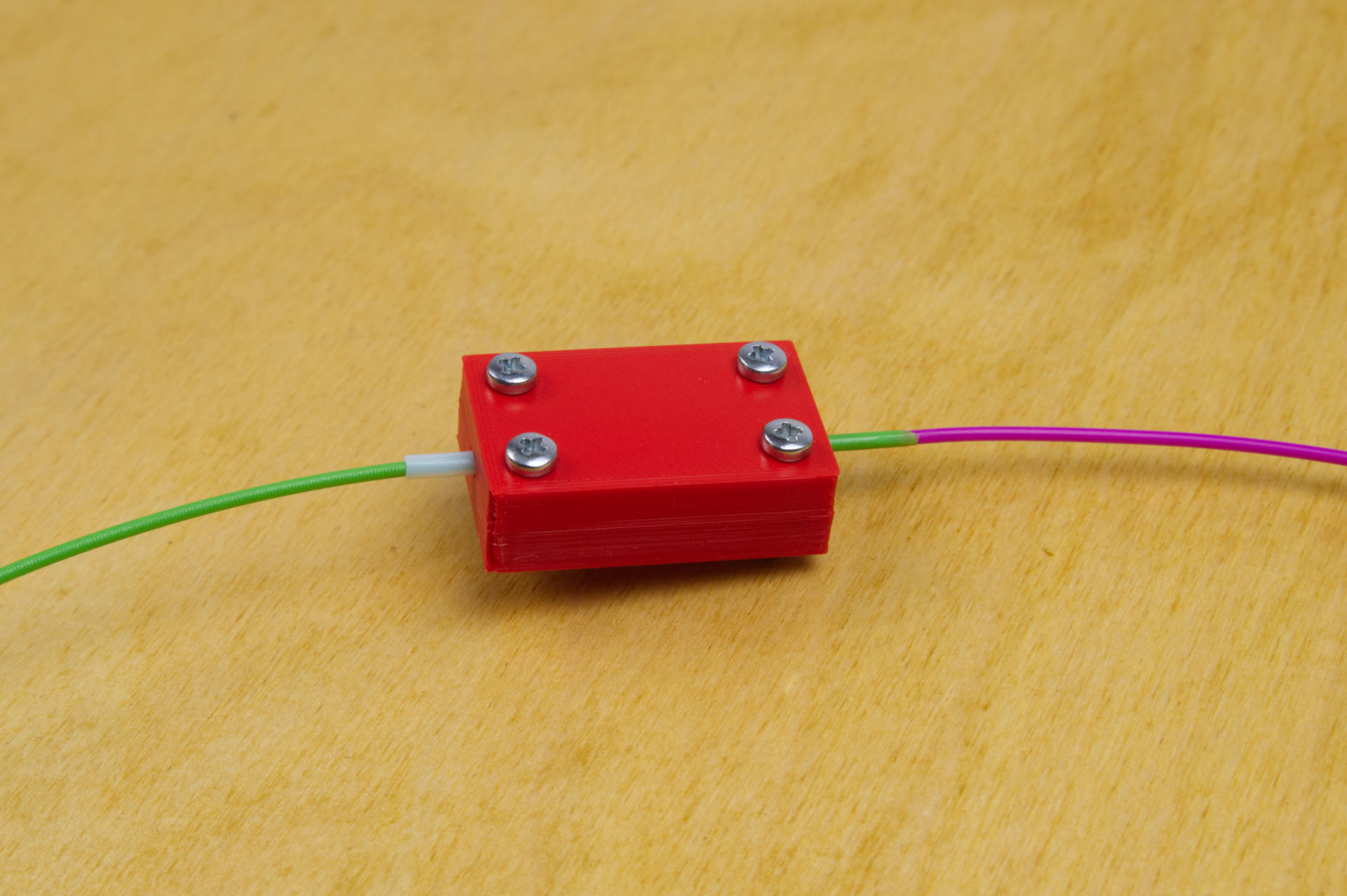
You’ll notice a long end and short end of the tube sticking out of the device. You’ll want the short end to be the business end. I probably could have trimmed the tube down on the back side but it’s okay to be a bit longer. Just keep the other end barely sticking out as shown.

I also used a vise to hold the device securely in place (I can see why Turnt use a clamp design) and also grabbed a candle… and of course, some filament!


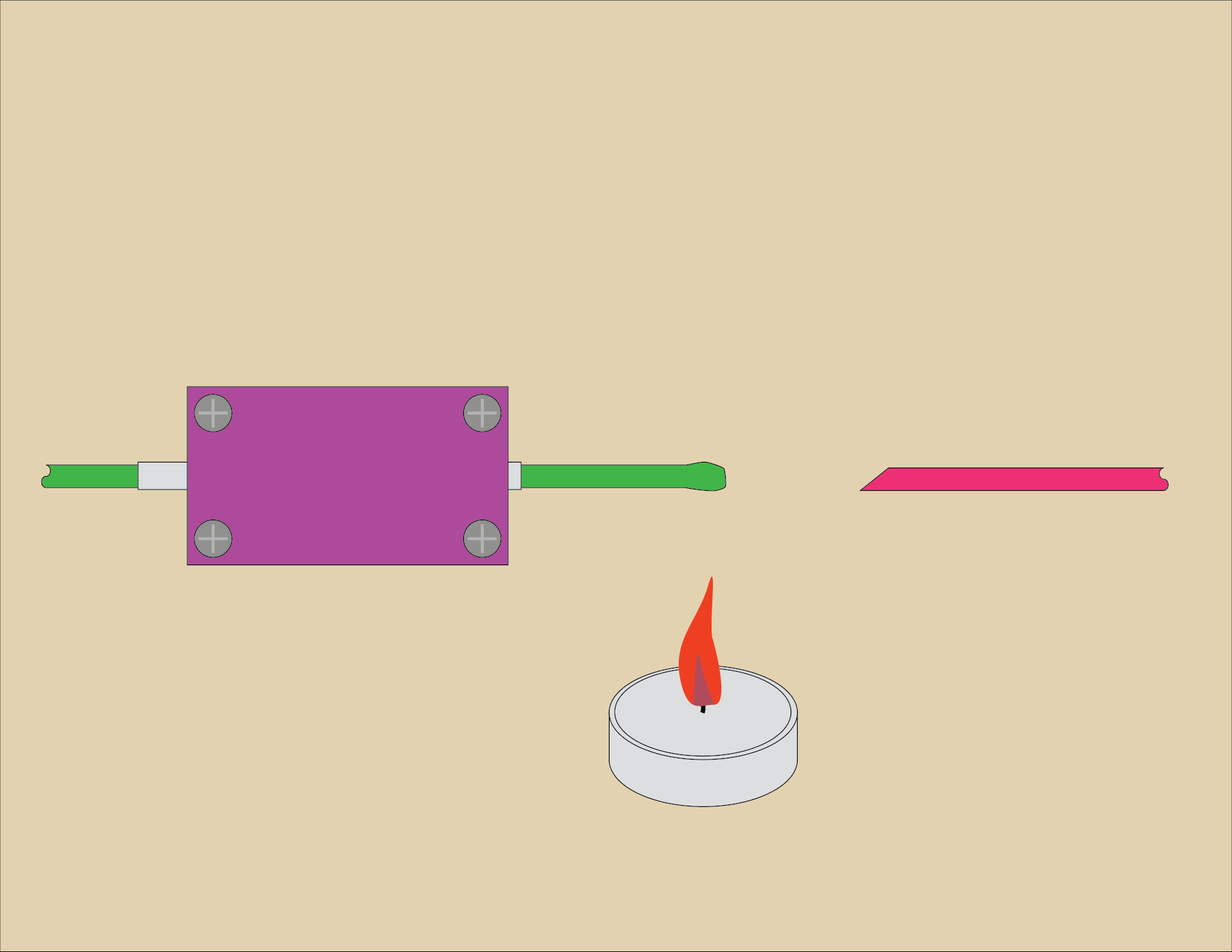
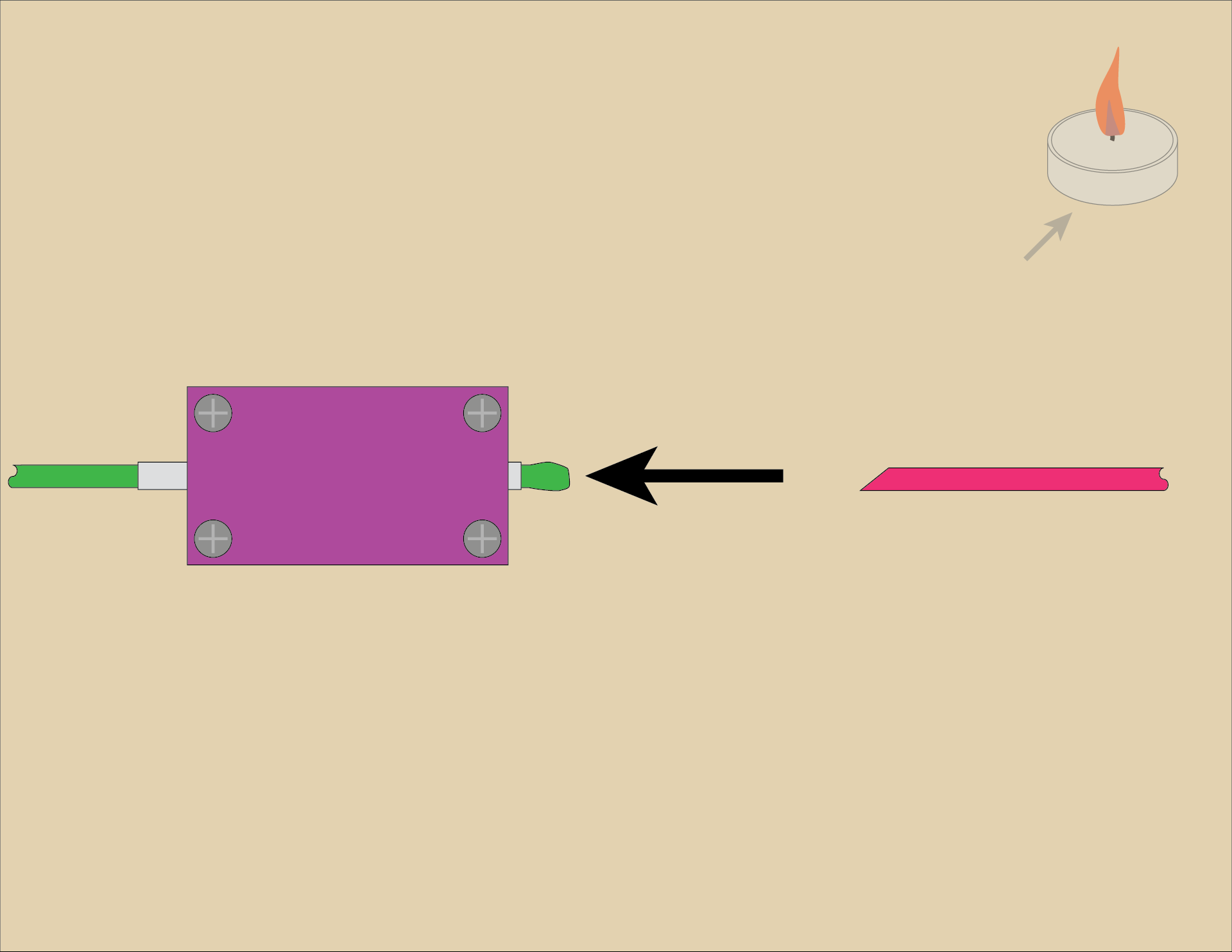
I’ll try to produce a quality video but in the meantime here’s an illustrated guide demostrating the technique. (And yes, I did mix up the colors as compared to the photos! You also won’t see the vise in the illustrations, so just pretend it’s there.)

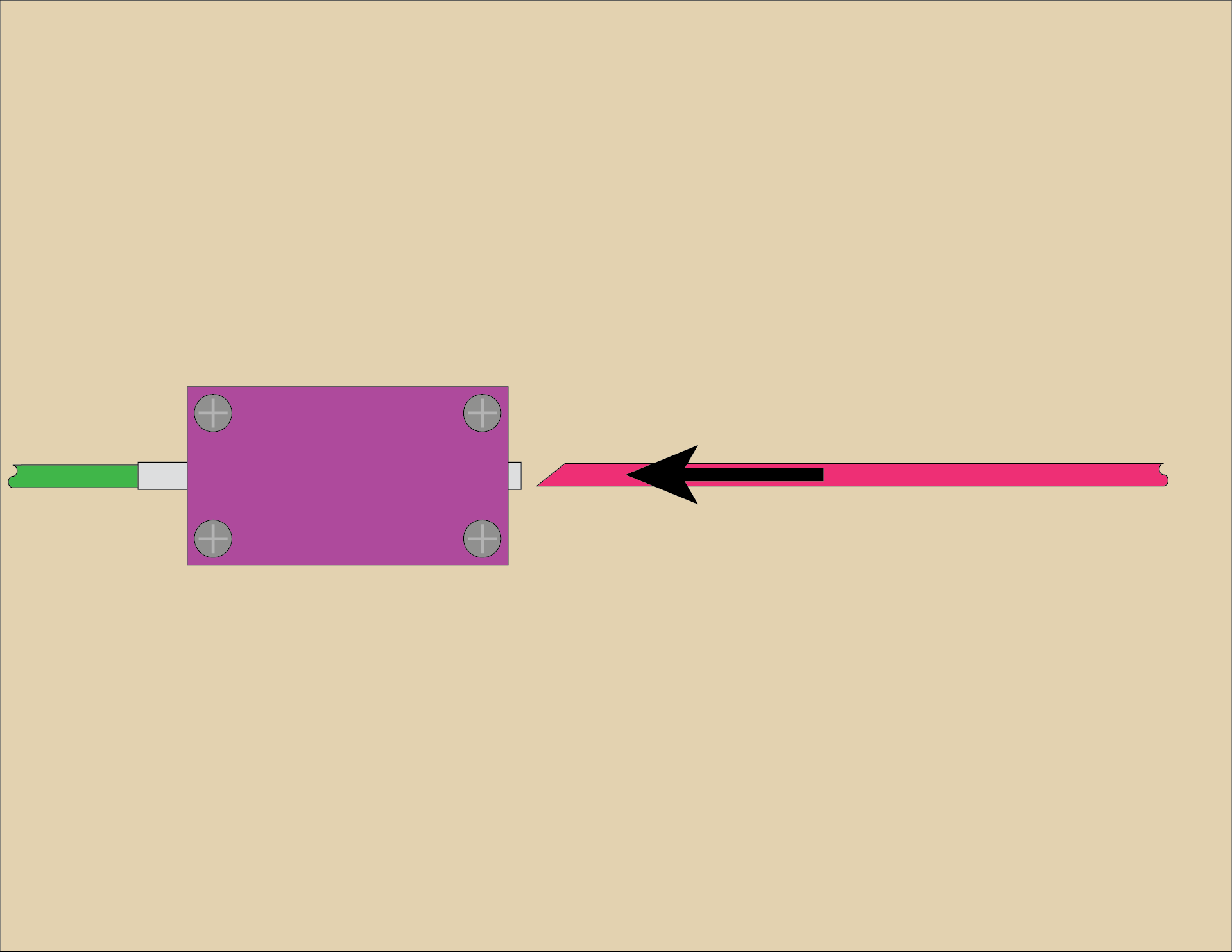
Insert a piece of filament from one side and slide it all the way through. It should have a flat cut end on it. This is the piece we will heat up. The other piece (on the right side) should be cut at a 45 degree angle. The angle is primarily to allow you to quickly and easily feed it into the tube without fiddling about.

Put the filament over the candle flame and it should start to soften. Don’t get it too close, or it will catch on fire and burn! Start with the filament further away from the flame and slowly move it closer. I think around 100mm is a good starting point.

Once you see the filament end soften into a blob pull it back into the tube… You’ll need to pull it in about halfway into the device. Practicing a few times will help you get it right.

At this point you may want to move the candle out of the way, or just blow it out for safety.

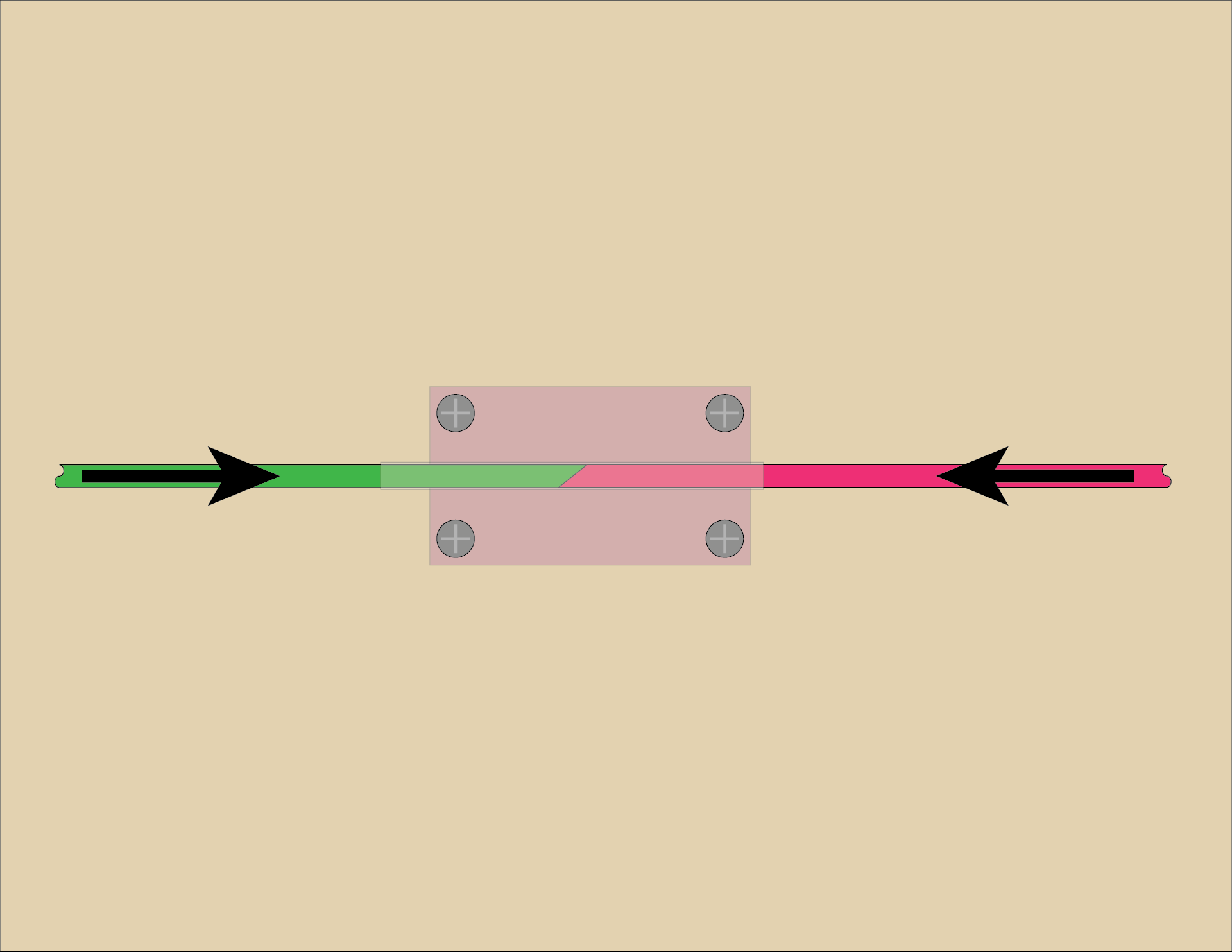
Once you’ve pulled the heated filament into the tube quickly push the other piece of filament (with the angled end) into the tube.

Now you should be using both hands, holding both pieces of filament, pressing them against each other. Push and hold. You don’t need to push with all your might, but give some good pressure. Wait a bit for it to fuse and then cool… 30 seconds should do it.

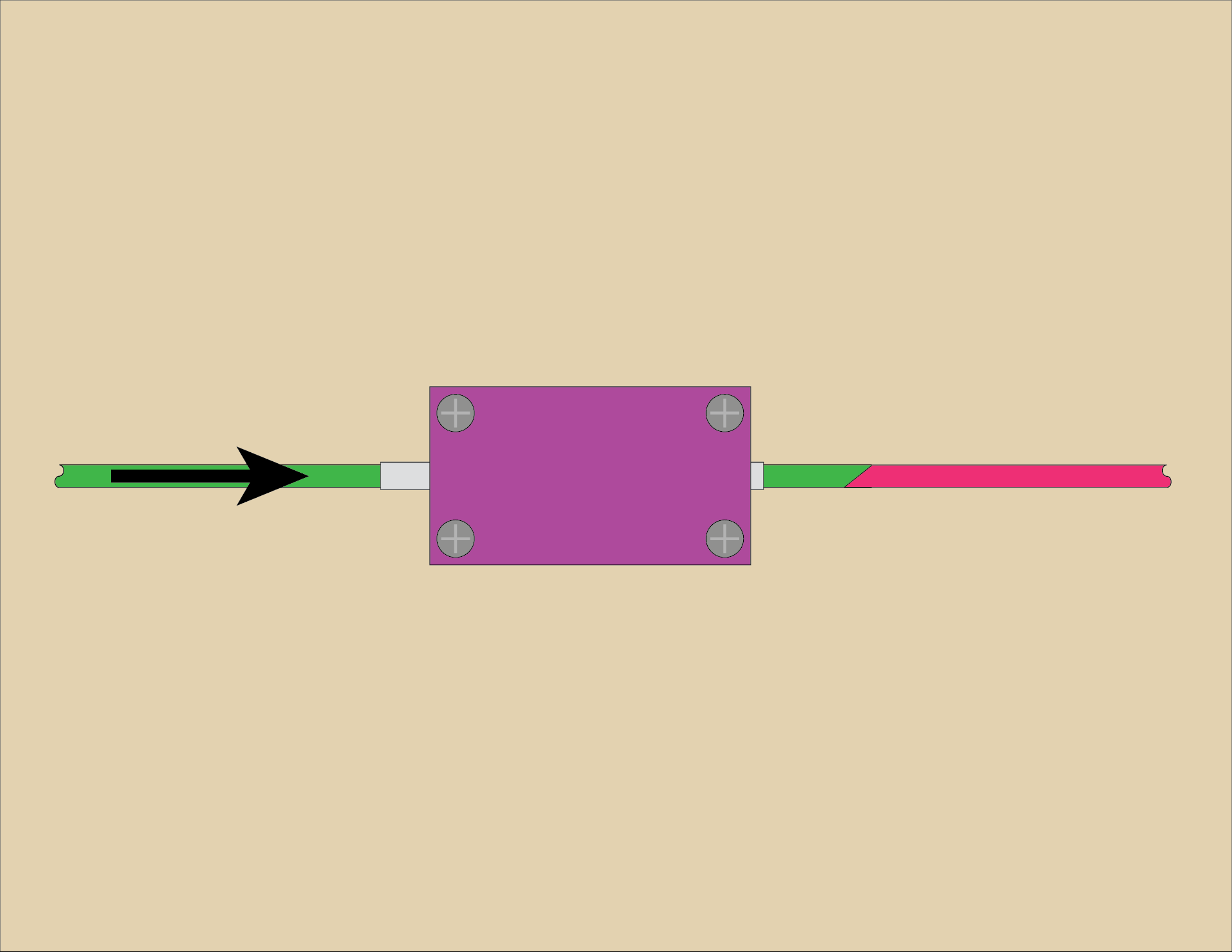
Now push/pull the filament out again, and inspect it. Give it a (light to medium) tug to make sure it doesn’t come apart. If it separates, cut the ends and try again.

If you find that you cannot push/pull the filament out of the tube you can loosen the screws to release the clamping on the tube, or separate the top and bottom pieces completely so the tube can be removed from the assembly. This can make it easier to slide the filament out. You will obviously have to slide the tube completely off of the filament piece. When doing this I’ve probably got a spool on one end so I’ll slide the tube away from the spool to free it from the filament and then spool it all up.

Using this method I joined about a dozen pieces of filament into a portion of a spool and then did some test prints. Are they the greatest prints ever? Probably not… Since I mixed multiple colors and brands together I’m sure the filament profile, which should be tuned for a specific filament, sort of goes out the window. Still, the results were completely acceptable and I’d rather find a way to use up all those short bits and unspooled samples I’ve collected over the years.

The Device
You can get the STL and .scad files from Printables.com – Simple Filament Fuser. Print it if you want to give this a try…

You’ll need four 3mm x 14mm (or longer) bolts and four 3mm nuts to assemble the device. You can probably use #4-40 bolts & nuts as well, or adjust the size of things in the .scad file to suit your needs.

If you end up making this and using it, please let me know. Did it work? Did it not work? What was your experience? Any tips or tricks to share?


Update: Don’t like the DIY route? This Filament Welder device is somewhat similar, but reading the reviews suggest you will need to shave/sand down your joints, and you may also benefit from a few of the tips I’ve shared in this post.

Categories
Uncategorized

The Ultimate CR2032 Battery Holder!

Apologies for the (mostly) joke title. I’m sure this is not the “Ultimate” CR2032 Battery Holder (as there are many) but I do think it’s a good one. Read on for my defense of this statement…

I came into the office one day and Josh said “Hey, I found this CR2032 holder and printed it, what do you think?” Which was… interesting, because I had been working on a design for a CR2032 battery holder. I didn’t finish it, for whatever reason (I probably started designing something else.) Anyway, I looked at the print and thought… I can do better!

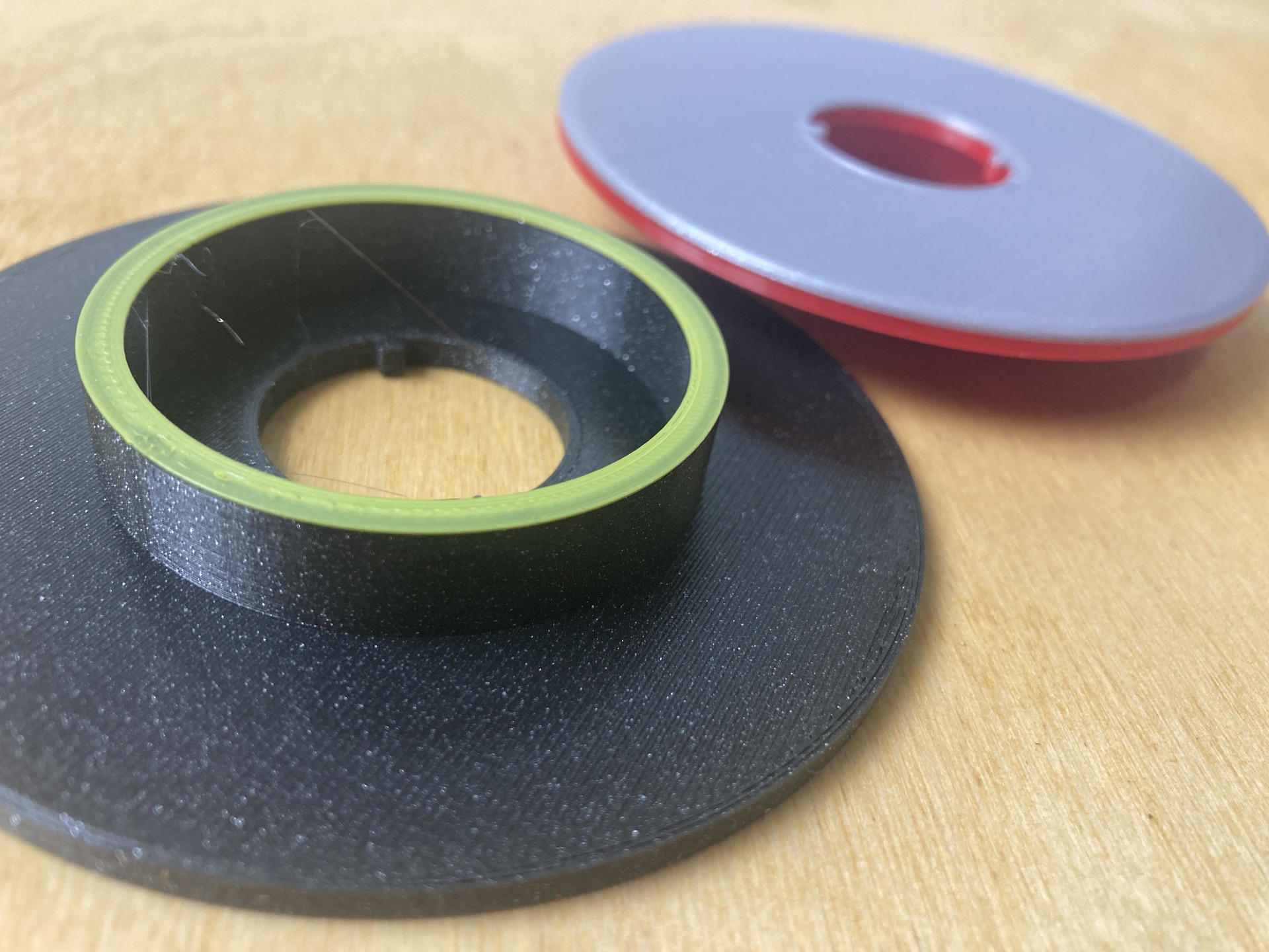
Above is the one Josh printed (in front) and the one I designed (in the back). The one he printed had the batteries a bit too close together, so you couldn’t grab one to get it out using your fingers. For my version, I spaced the batteries a bit so you could grab one. (Note the batteries sort of “snap” in place, they aren’t just held in by gravity.)

My design was still not great… but after about a dozen revisions I had something good.

The design is parametric, and with the OpenSCAD file you can choose how many batteries you want to hold, and (slightly) adjust the space between them.

But the real beauty of this design is that you don’t have to space the batteries enough to grab one with your fingers… With this version you pop them out from the bottom! The batteries snap into place to hold securely, and you press them to get them out. (Check out the video below.)

There’s one more bonus feature… If you print two the same size you can use one as a cover.

Add a rubber band (or a piece of tape) and you’ve got a secure battery holder you could toss into a bag with little worry of any batteries shorting out. Neat!

But wait! There’s more to this story… At some point I asked Josh about the file he found, and he pointed me to the Thingiverse page, at which point I said, “Oh, I know the guy who designed this.” and he said “Of course you do.” to which I replied “Yeah, I hired him years ago for some exhibit work, and I’ve worked with his partner to produce Maker Faire Orlando.” and yeah, sometimes the Maker World seems a little small. But wait… also, I grabbed the files Adam posted and realized he did post a parametric OpenSCAD file! It still didn’t have the pop-out feature I added, but it did allow for changing the spacing of the batteries. (Josh just printed the STL example file that was there.)

So to wrap up, you can see the guide on these at learn.browndoggadgets.com, grab the files from Printables or from GitHub, and do whatever you want with them! We now use these at all the events we do when we have supplies out on the table, and they’ve been a huge improvement to just spilling out batteries on the table or keeping them in the (difficult to open) packaging.

Categories
Uncategorized

Hex Driver Handle

I’ve seen a few handles that convert a hex key into a “screwdriver” style tool, so I figured I would make one. (I’m sure there are better ones, but this one is mine!)

This one is two pieces. The main handle has a slot so you can insert the hex key, and then a piece to put into the slot. (Which I call the “Slot Filler” of course.)

When I printed this on the Prusa (not pictured) it came out perfect, and the slot filler filled the slot… perfectly.

When I printed it on the Maker Select Plus (the red version in the photos) it… well, fits, mostly… sort of. Hmmm. I had to X-ACTO knife away the blobs on the end. (Sorry, but the Prusa just prints better!)

You could always glue the slot filler into place I guess. It’s a wedge so it should “wedge” in place. In theory…

The first version had no slot filler, and no hole for the short end. I just smashed it into the slot. I figured making it removable might be a better option though…

Maybe it’s not a god idea? I don’t know. I did widen the slot a bit and added the slot filler. I just like designing these things and testing them out.

You can get the STL and .scad file from Printables.com – Hex Driver Handle (2mm). Print it if you need it!

Categories
Uncategorized

OpenSCAD Local / Modules Variables

I will start with the disclaimer that I’ve never held the title of “Software Developer” or even “Programmer” and my career has been built on being a “Hacker with Many Hats” kind of person. So I tend to go broad and not go deep on a lot of things. I’ll confess, I’ve used a fair amount of global variables in my code, probably some where I should not have. As an old-timer Perl Hacker, it’s… meh. My code was often quick & dirty to get the job done, not elegant and meant to last.

That said, even though I read an entire book on OpenSCAD I somehow had it in my mind that variables in OpenSCAD could not be changed during run-time, as it were. OpenSCAD is… weird, but I’m okay with that. Supposedly variables in OpenSCAD should be thought of as “override-able constants” rather than as variables in the traditional sense.

Also, I’ll admit that often I find examples of code either poorly written or too complex for me to immediately grasp. (I’ll let you decide which is which.) Here, you can read about scope in OpenSCAD User Manual/User-Defined Functions and Modules and OpenSCAD User Manual/General.

Or you can look at my example above… Because yes, you can change the value of a variable in a function / module! Variables are local within a module!

Here’s the demo code shown above. I am guessing 98% of software developers are saying “Duh!” right now… so this post is for me, and people like me, who may have missed this, may have been confused by this, or just needed a simple demo.

Categories
Uncategorized

Wire Spool Holder

I use these spools of silicone wire and they come in a cardboard box with a hole to feed the wire through and every damn time the wire goes back into the box and I have to open the box and feed it through again and wow it’s a pain! This is an attempt to solve that…

Like some of my other designs I wanted a modular thing. The wire comes in six spools/colors but rather than one huge print each spool has its own holder. This makes sense to me. I thought about ways to interlock them, but eventually decided to just add screw holes and mount them all to a piece of scrap 1/4″ plywood that was near the laser cutter.

The hole the wire feeds through is just right for this wire. YWMV (Your Wire May Vary!) The OpenSCAD file allows for adjusting the hole. An X-ACTO knife or drill bit could also be used to fine tune things.

Advantages of this design? It is stackable. I can put stuff on top of it. (Maybe more wire spools?) I can pick up the whole thing easily. There is not one rod holding all spools, and you can easily remove/replace a single spool.

So far I’m liking this thing. It’s similar to my Chonky Solder Spool Holder. It took about four revision to this before I had the final version.

Here’s the first attempt. It was too difficult to feed the wire through the hole, so the hole got moved up and the half-circle notch was added to allow getting a finger in there to feed the wire through. The bottom lip was also added to allow for mounting to the board with screws.

You can get the STL and .scad file from Printables.com – Wire Spool Holder. Print ’em if you need ’em!