Categories
Uncategorized

Power Mac G5 Side Panel Wall Hanger

For me, 3D printing represents niche custom things that solve problems, sometimes for a few people and sometimes for just one person.

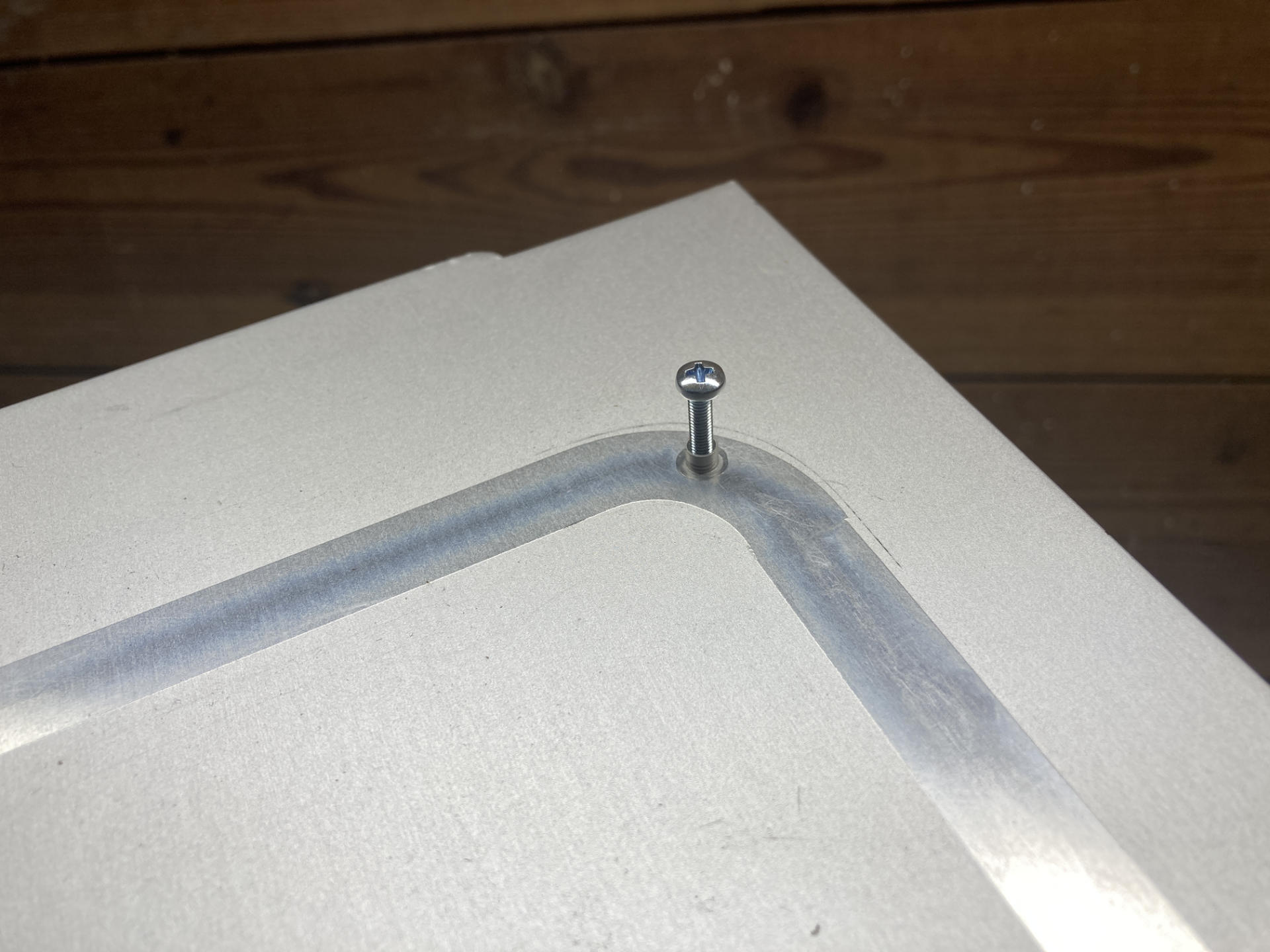
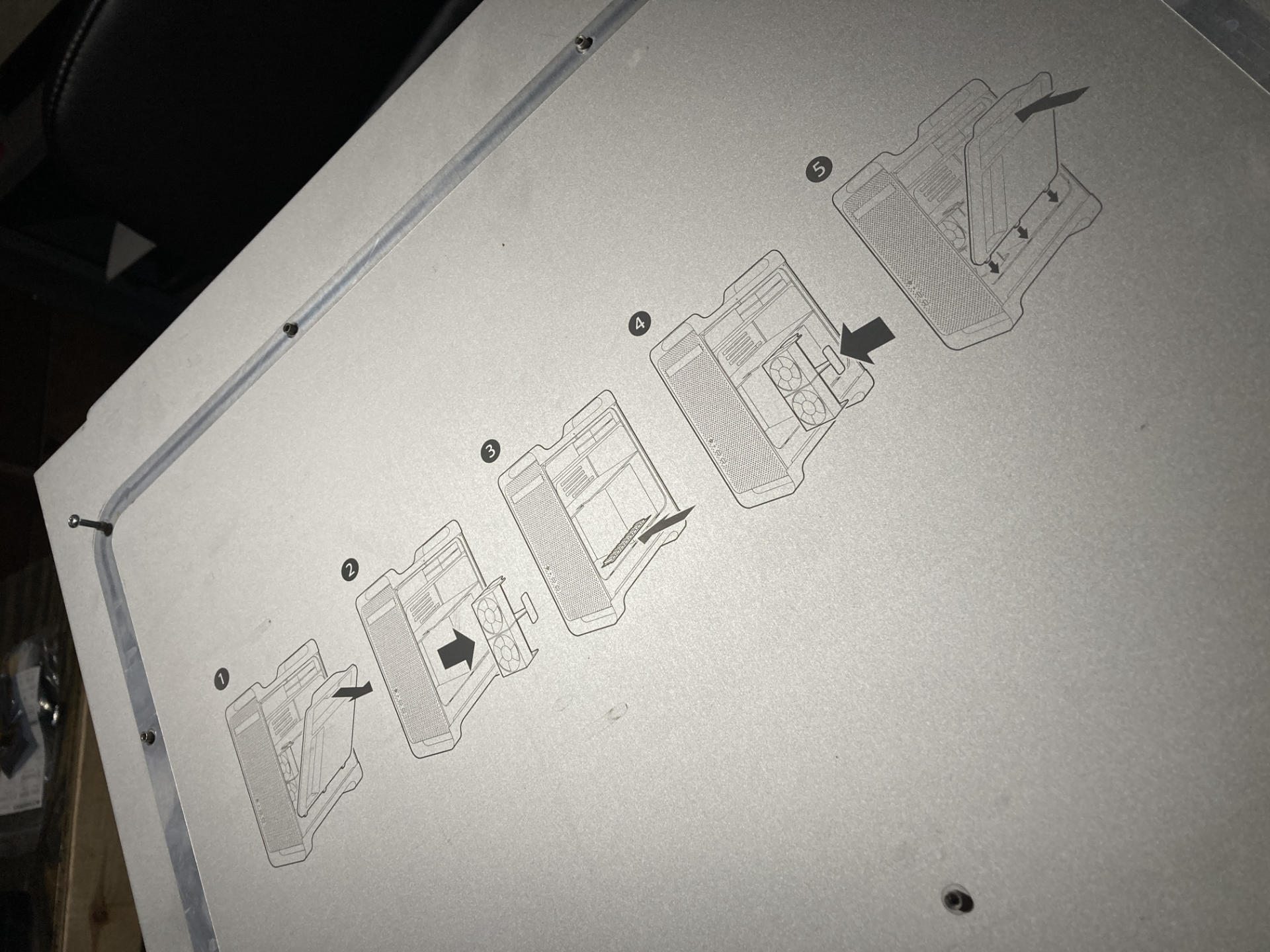
While cleaning the shop I found this old side panel from a Mac… well, a Mac Pro, or a Power Mac. I wasn’t actually sure, but I got some help. (It’s from a Power Mac G5!)

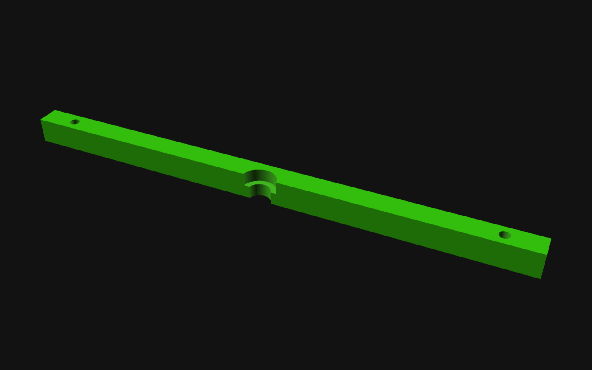
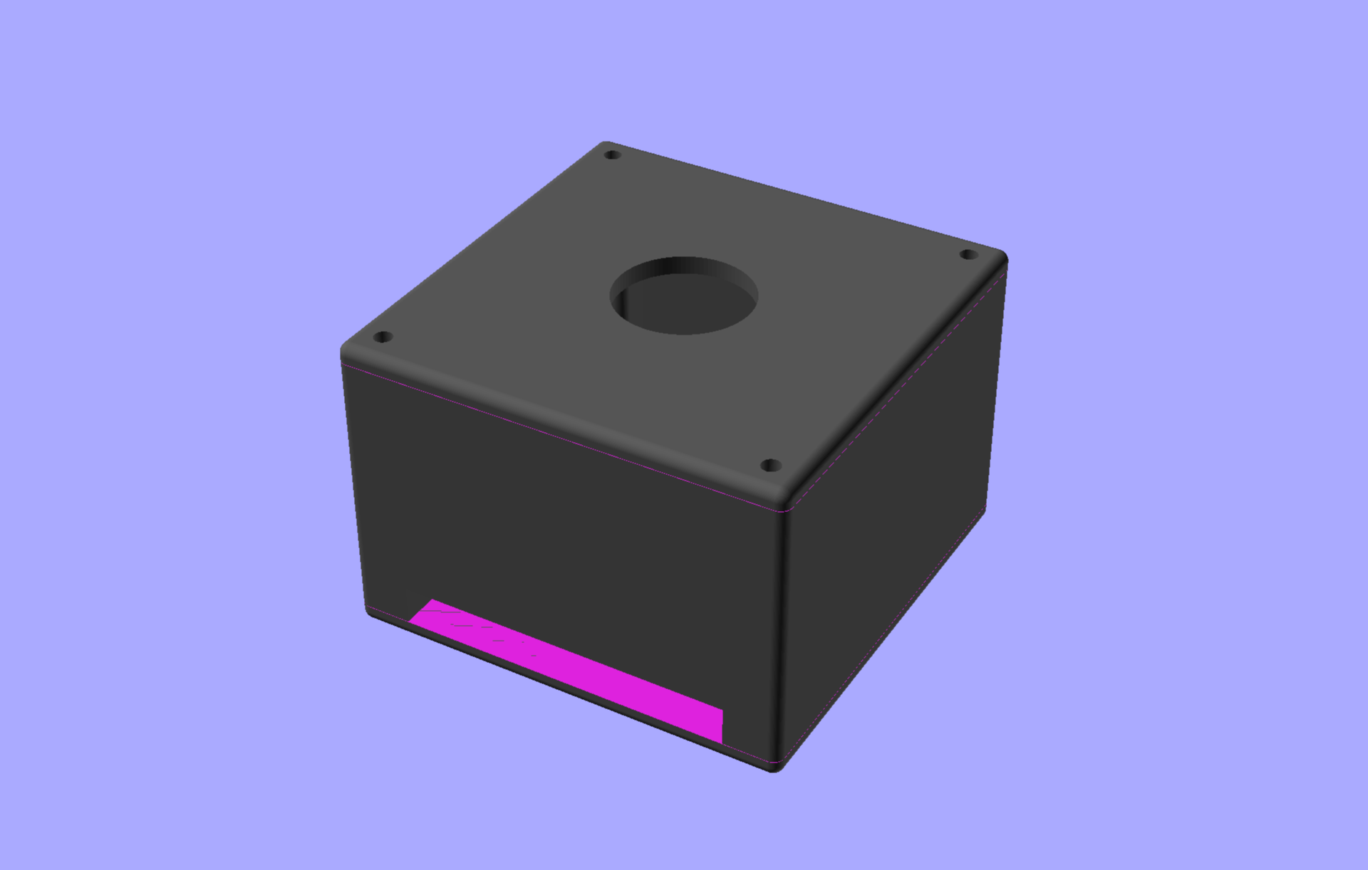
I had wanted to hang this on the wall years ago, so I figured now was the time. I took some quick measurements, spent a few minutes in OpenSCAD, and 25 minutes later had a piece that fit and was suitable for hanging.

I used four 3mm x 14mm bolts, two to hold the bracket in place, and two at the bottom of the panel so it would sit away from the wall a consistent amount.

I honestly don’t know if anyone else will ever use the file, but I figured I would share it anyway. So I did.

You can get the STL and .scad file from Printables.com – Power Mac G5 Side Panel Wall Hanger. Print it if you need it!

Categories
Uncategorized

OpenSCAD Viewing Angles

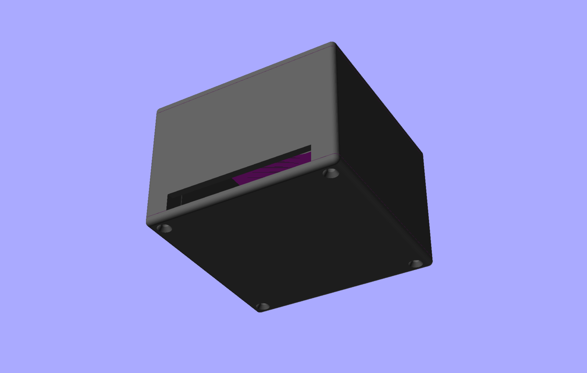
I’ve found that more and more I am exporting images from OpenSCAD, and while in the past I was satisfied with just spinning the object to an angle and exporting a PNG file, I’m now doing more step-by-step things where I want consistency and don’t want things jumping around. Instead of carefully setting the view with the mouse and doing all the exports, I now set the viewing parameters directly in the file, because you can do that in OpenSCAD…

Time to go back to the OpenSCAD User Manual! While the Cheat Sheet is an excellent resource, I find myself hitting up the manual a lot more frequently lately. The Cheat Sheet will show you this of course:

$vpr viewport rotation angles in degrees
$vpt viewport translation
$vpd viewport camera distance
$vpf viewport camera field of view

And that’s what we need! So over to the manual section for $vpr,_$vpt,_$vpf_and_$vpd.

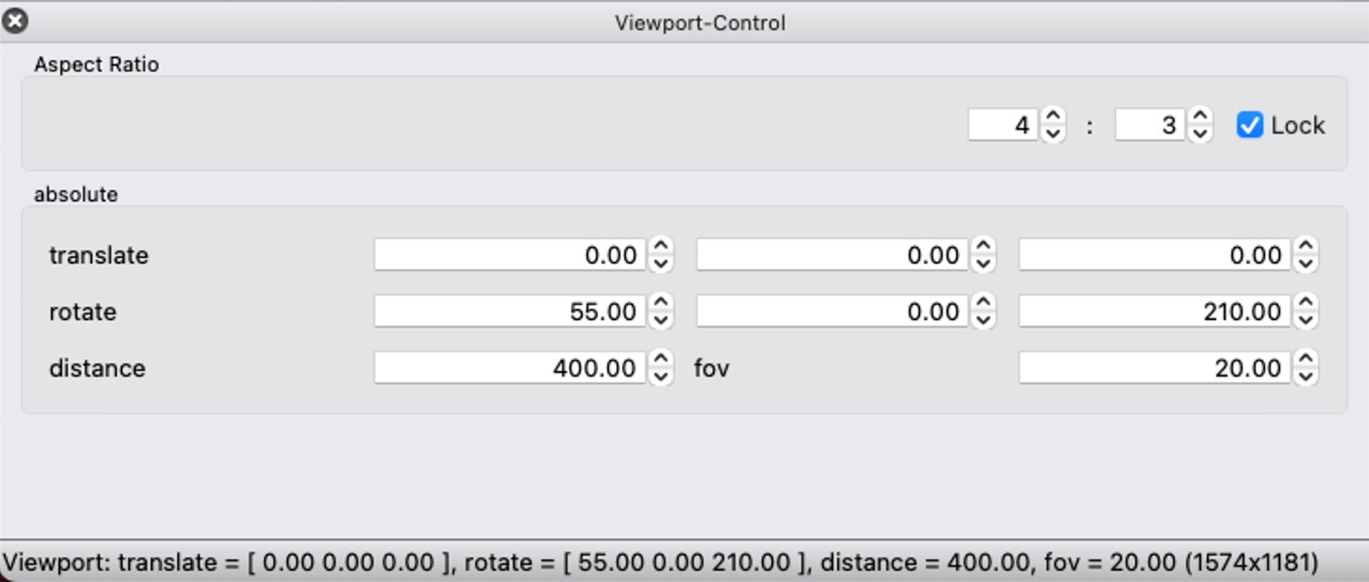
Pop open that Viewport-Control in the Window menu and look at that… it shows you values and you can change them…

(Note: You can also set the aspect ratio, and lock it. Sweet!)

But the real powerful bit is that you can just set those parameters in your code. When you preview your code it will set those values and you get the same viewing angle, rotation, distance and field of view each time. Brilliant!

You can see my commented out code for the bottom versus top view on line 37.

I love finding stuff like this and them implementing it into my code… It’s probably not some amazing killer feature, but it’s one more nicety that helps me keep things consistent and adds a bit more power to what I can do with OpenSCAD.

Categories
Uncategorized

Circular Positioning in OpenSCAD

This post is about a problem… it’s about looking at a problem from the wrong angle, and eventually realizing it.

I wrote some code in OpenSCAD, and then I wanted to change something and I could not figure out how to get the positioning right. I should confess I am terrible at maths. In school I took geometry, but never did calculus or trigonometry, and know almost nothing about those areas of mathematics.

Since I tend to work in Cartesian coordinate systems I think about moving things in X and Y. Left, right, up, down… Sure, there are angles, but they can be difficult. But maybe they shouldn’t be…

Here’s what I wanted to do: Create a circle with three smaller circles evenly placed into a triangle. Now typically in OpenSCAD I move things around in the X and Y and for the mostly rectilinear things I design (mostly enclosures) that’s simple, but circles can get weird. So what I tried to do was move each of the holes along the X and Y axes, but I could not get them evenly spaced…

See, this is easy for me. Four things, evenly spaced. Everything moves from the center an equal amount in X and Y. My simple maths brain has no issue with this. I’m so used to doing it this way I can bang it out without any thought. But this way (while simple) is sometimes not ideal.

As is often the case, I took to Mastodon with my problem, because there are people there much smarter than I am… Luckily @GeekAndDad was on the case! While he was busy doing the hard math I was distracted with some other projects… but when I returned I realized I knew how to do it… because I did it ten years ago! Check out this post about Derby Wheels.

Okay, so I did it before, but didn’t have easy access to the code I had written, but remembered how it worked, so I banged this out:


// Position things in a circular pattern in OpenSCAD

$fn=100;

howMany    = 3;
distance   = 10;
holeSize   = 10;
startAngle = 30;

difference() {

    // create the object
    translate([0,0,0])
        cylinder(d=40, h=3, center=true);

    // loop around in a circle and difference some holes
    for(variable = [startAngle : 360/howMany : 360+startAngle]) {
        rotate([0,0,variable])
            translate([distance,0,0])
                cylinder(d=holeSize, h=3.1, center=true);   
    }
}

(You can also find this code in my gists repository.)

Here we go! Three holes, evenly spaced… We do this by rotating around the center and placing the hole X number of units from the center, every X number of degrees. You can set the number of holes howMany, the distance from the center, and of course the holeSize and also the startAngle which helps rotate the whole set into something that matches up properly.

Hey, you can even do four holes! They are all still evenly spaced from the center…

You can do seven holes… The bit with 360/howMany does the maths to determine how many degrees there are before adding another hole.

Heck, you can even do just two. Want them top and bottom instead of left and right? Just change the startAngle appropriately.

You can put the holes on a square instead… or a rectangle, or anything, really. And they don’t even need to be holes… I just needed holes for this specific example.

Another square with some holes…

And yet another square with some holes… This time with a different startAngle set.

Those holes look a little large… can we make them smaller?

We sure can! Look at that… Obviously you are not limited to just making circles, and this technique of using a for loop to put things around the center of an object can be expanded in many ways. I just wanted to share this recent remembrance so I can find it again when I need it!

By the way, these OpenSCAD renders were all done using my Cyber Night theme for OpenSCAD.

Categories
Uncategorized

Hardware Gridbox

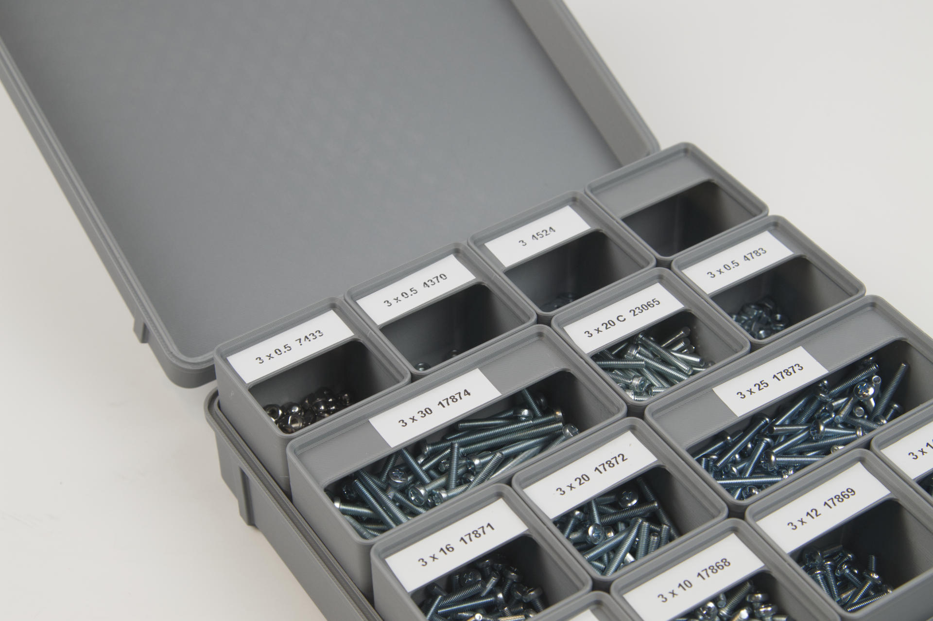
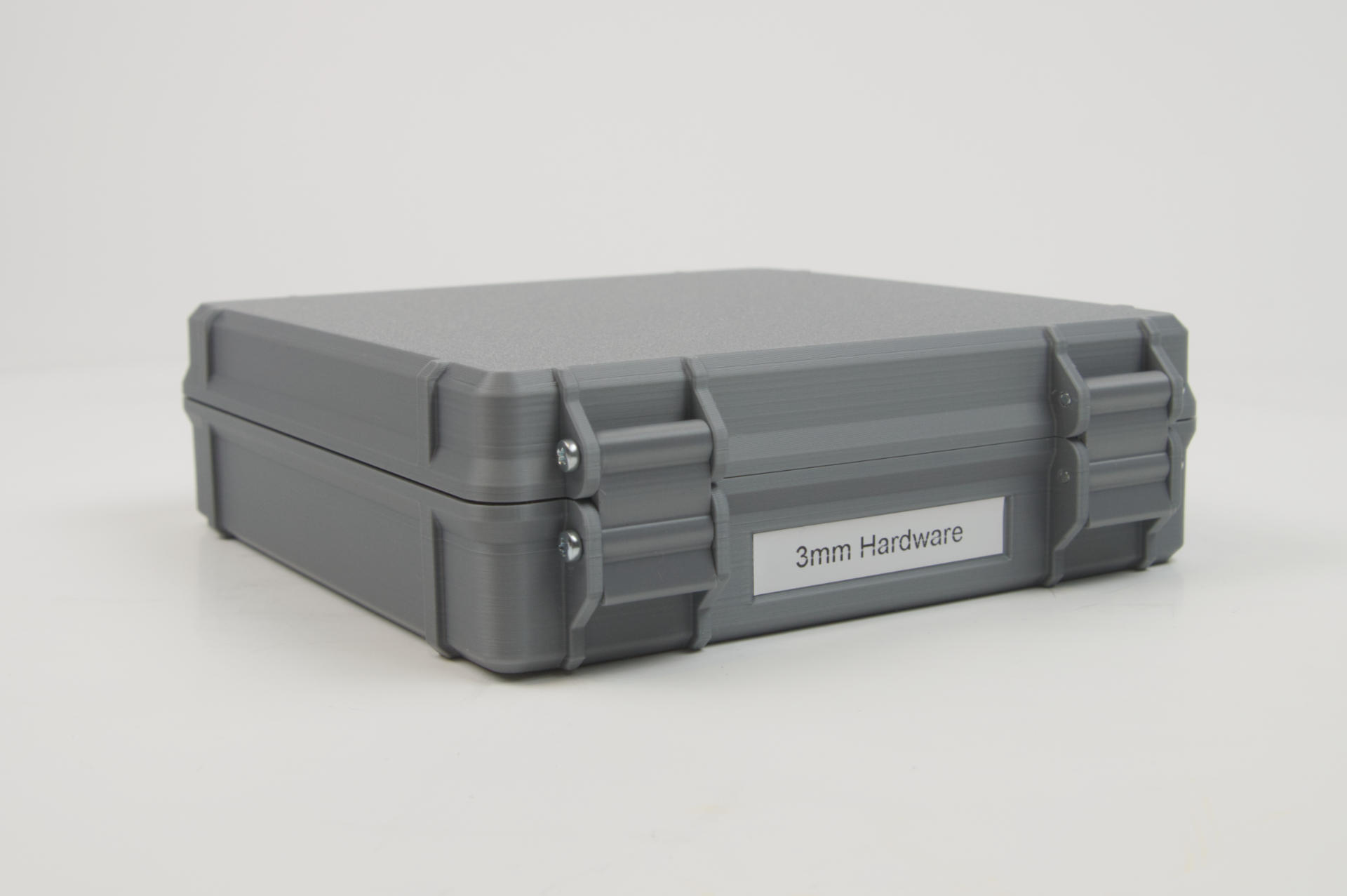
After I got the Bambu Lab P1S I stress tested it a bit with the 3D Printed Pegboard but before that project I actually printed this Gridbox which uses the Gridfinity organizational system.

The way Gridfinity works is that there is a grid (duh) and you print bins or other “things” that fit into the grid. The bins can be 1×1 or 2×1 or 4×4 or whatever fits into the grid. I actually used Gridfinity Rebuilt in OpenSCAD to generate these little bins because I prefer OpenSCAD to Fusion 360.

I scaled the height of the bins to the internal height of the Gridbox. I can tip the box over and all the hardware stays where it should. Almost. The washers are small and thin enough they occasionally end up in the top part of the bin where the labels are. I could probably solve this by gluing a piece of foam inside the top lid so it closes and provides just an extra bit of cushion. I may try that… If I did this again I would perhaps alter the bins just a bit to have flatter tops since I won’t be stacking these bins.

This really is a great way to store all of my 3mm hardware. As I’ve mentioned in other recent posts, I’m really trying to organize my shop and maximize efficiency. Before this I kept all the hardware in individual bags and then in a larger bag, which meant pulling out all the bags, grabbing the one I wanted, opening that bag, getting the hardware, etc. Again, let’s make this easy. I can also see how much hardware I have in each size easily, as compared to being stuffed into bags.

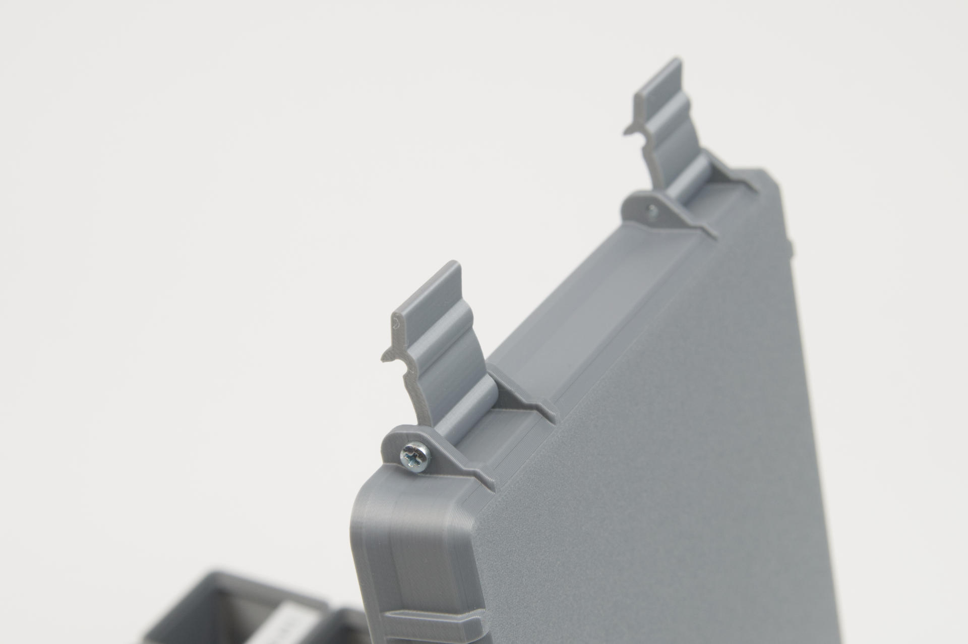
This Gridbox is a really nice design. I used the 4×4 version and will probably make another for my 2.5mm and 2mm hardware. There’s also a version that allows for a clear acrylic laser cut piece to fit into the top lid so you can see what’s inside. I don’t need that for my hardware, but it is a useful feature.

The model is based on the Rugged Box (Parametric) by Whity, which sadly is only parametric if you use Fusion 360. Sigh… I did find this Parametrizable Rugged Box (OpenSCAD) by Dochni but I don’t love it. I’ve started to try improving the code to do what I want but then I just started to write my own which I haven’t finished yet. (Note: See Rugged Parametric Box in OpenSCAD for a great new model!)

Besides a few things that give it away as 3D printed, this is another print that just does not look printed. The quality of the print is so good, and the design is top notch, so yeah… we’ve come a long way since 2011.

Anyway, the 3mm hardware is now sorted! That said, I have been using my Parts Tray with Sliding Lid for over a year now and I’ve been quite pleased with it. I may make a few changes to it though, as there are a few specific pieces of hardware I like to have at the ready.

Categories
Uncategorized

Filament Containers

I’ve been working on reorganizing (or just “cleaning”) my workshop and that’s forced me to look at the processes and tools that I use. In the case of filament storage I used to just stick an opened roll into the plastic bag it came in, toss some desiccant into the bag, and then shove it into an old filament box. It works, but I find it annoying. The bags are a pain, and once they are in a box I don’t know what color is in what box.

So I looked around for some filament storage solutions that involved clear containers. This STACKER F-Box is about $50 USD and I don’t need a container I can print from. This Kingroon is under $30 USD, but again, not quite right. There are these PrintDry containers but it’s $75 USD for 6 of them and I’ve seen a few non-favorable reviews…

Ultimately I got a six-pack of these PRAKI Dry Food Storage Containers for less than $25 USD. And every roll of filament I have actually fits. (About $4 USD per container is not bad at all!)
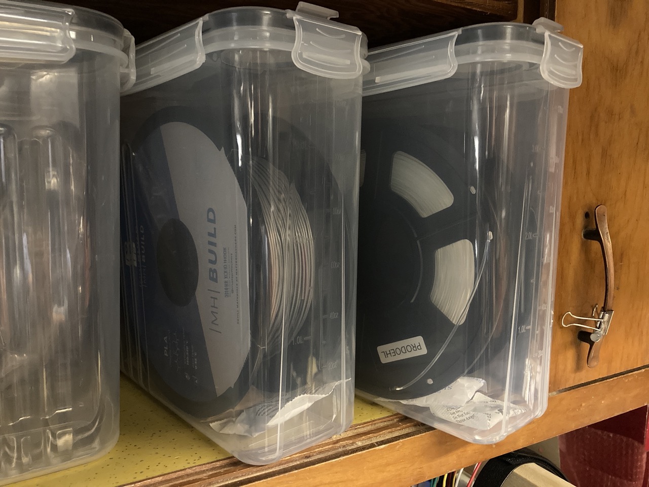
I was concerned the containers would be crap, or not air-tight, but they’re probably more air-tight than the plastic bags I use over and over again and just fold over and tape shut. These work well for my needs, fit on my shelves, and are nice and clear so I can see what filament is inside. I remember that there was a huge tub at Milwaukee Makerspace that could hold a dozen or more rolls, but that’s not a good solution for my needs, so these individual containers work quite well.

I think this is a good example of COTS (commercially available off-the-shelf) where you can find an existing item which has a specific purpose, and then repurpose it for your needs, and it ends up being less expensive than the item that was specifically designed for a need. So while a few companies created filament storage containers it makes a lot of sense to just repurpose something like a food storage container, of which there are hundreds (or thousands) of different varieties.


Update: In this thread Mastodon user @GeekAndDad pointed out these large IRIS 44 Quart WeatherPro™ Containers they use which can each hold 7 rolls, so the 2-pack will set you up for 14 rolls of open filament! It also looks like there are a variety of other sizes if you prefer the “large container” approach.


Note: This post may contain Affiliate Links. Read More.