Categories
Uncategorized

The LED Burns Bright

Disclaimer: I have destroyed light emitting diodes (LEDs) in the past. Typically on purpose, by feeding them too much voltage until they burn out in a bright flash. It’s fun to do if you’ve got a variable power supply with a dial and can slowing crank up the voltage.

That said, this is about trying to destroy an LED without trying to destroy and LED. (Or maybe, trying to not destroy an LED but still breaking the rules.)

The rules you say? Yes. As in, you need a resistor when connecting an LED to an Arduino. This is just, like, a fact. You can get away with putting a resistor-less LED on an Arduino for testing, or learning, or a quick demo, but to do it right, always add an appropriate resistor inline.

There’s a web site called LEDCalc.com that helps you determine the appropriate resistor for the LED and voltage you are using. Tell it you’ve got 5 volts, one LED with a voltage drop of 2.0 volts, and want to give it 20 milliamps and it will tell you to use a 180 ohm resistor. (There’s fancy maths to figure this out as well, but I’m an artist who does not excel in maths.)

In the photo above you’ll see a (very bright) yellow LED connected to an Arduino Nano. (This Nano specifically is manufactured by Elegoo.) I have no resistor in my circuit, I have nothing else connected, just a single LED on a single pin, with a digital write to turn it on at full power. (As it were.)

Okay, so at some point the LED will be destroyed, or the pin on the Arduino will be destroyed, or the Arduino itself will be destroyed, or some component will fail. But… when will that happen? I’m a week into this experiment, and so far, all is well. Will it take a month, a year, a decade? Is the time to failure completely unknown, and completely random. Is it pure luck that this works, and it could fail any second now? Do I need to blink it on and off to get an inrush of current to the LED to stress it more?

I found this Arduino MEGA with 27 LEDs connected to 27 different pins, which I used for testing, and it seems fine as well. Granted, I don’t have all LEDs on at the same time for any real length of time. It’s a blinkenlights thing so lots of off time and some on time.

I’m now really tempted to change the code so it just turns on all 27 LEDs at once for an extended amount of time. I’m a bit curious about this whole thing now. I understand the reasoning behind current limiting resistors, but I’m wondering how that comes into play in the real world. One of the trickiest things I’ve dealt with when designing circuits is that they should work, they work on paper (or on the screen) but in the real world something goes wrong. EMF, physics, gremlins… whatever. Something you don’t expect comes along and screws things up… But this seems like the opposite, where we plan for what should/could go wrong, but then it doesn’t.

I probably need an actual Electrical Engineer to walk me through this one…

Categories
Uncategorized

Game Boy Camera Dumper

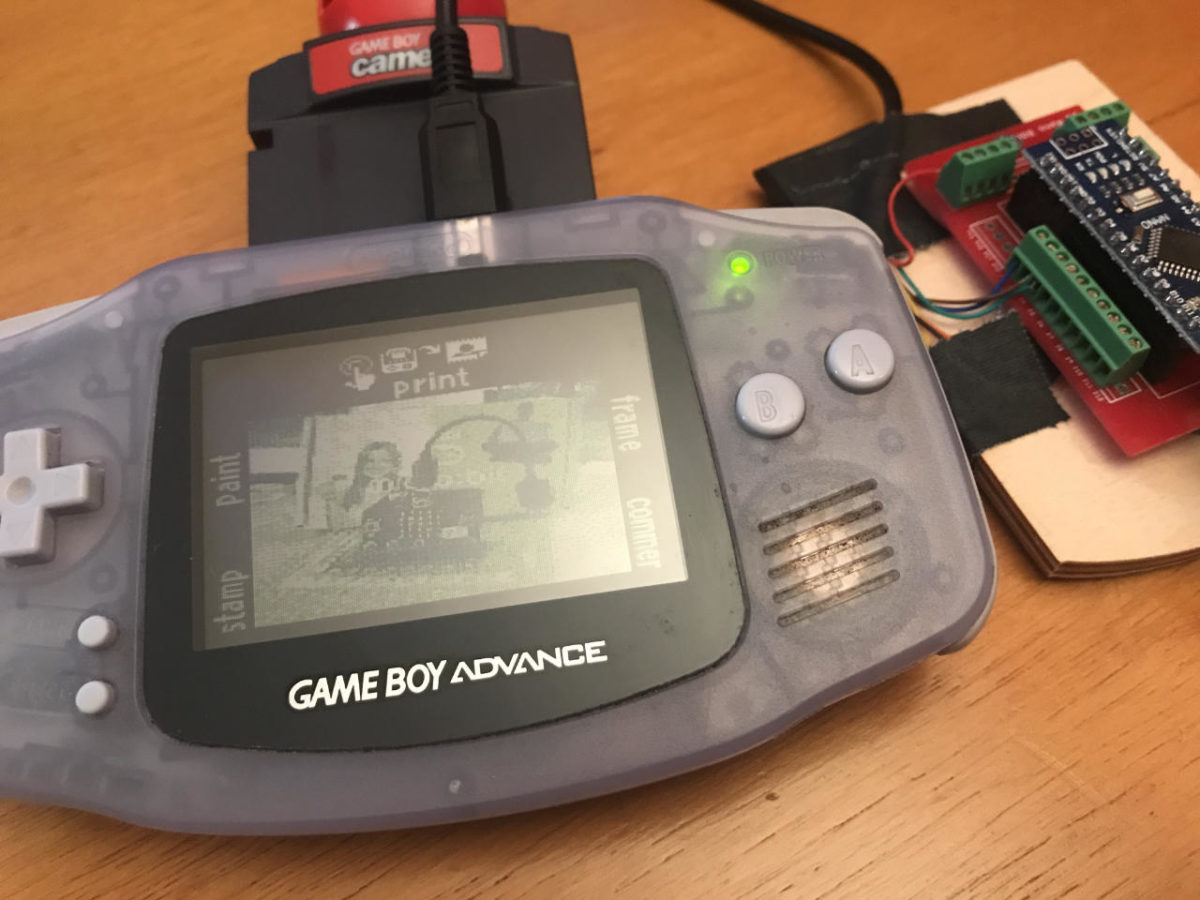
As previously mentioned, I finally got my Game Boy Camera up and running with the ability to transfer images to a computer. In this post I’ll outline the method I am now using to do that, which is an update from the first post.)

I put the code I am using on Codeberg in a repository called Game Boy Camera Dumper. (I wasn’t sure if I should use the word “transfer” or “capture” instead of “dumper” but I’ve always been a fan of Perl’s Data::Dumper module, so that clinched it.)

You’ll need Python3 installed, along with the pySerial and argparse libraries. pip (The Python Package Installer) should get those installed easily enough.

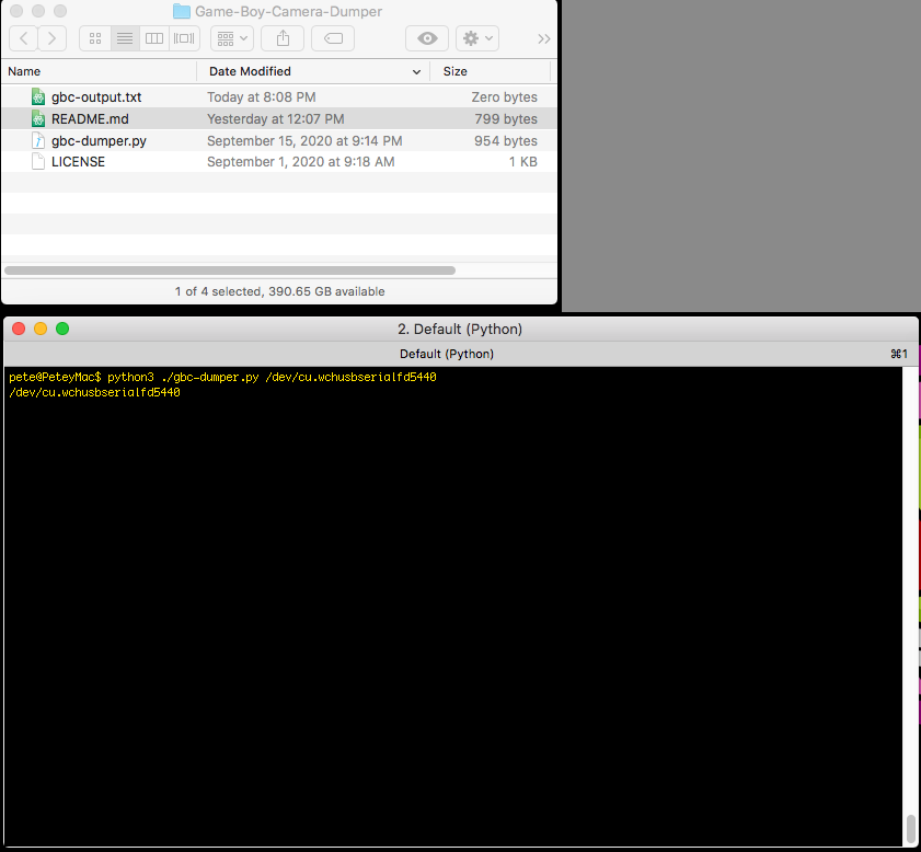
Once you’re ready you type python3 gbc-dumper.py /dev/tty.wchusbserialfa440 in the terminal (after you are in the right directory) and wait for the magic to happen… (And yeah, you don’t type /dev/tty.wchusbserialfa440 part unless that’s the USB port on your computer that your Arduino shows up as. On Windows it’ll be COM3 or something else, on Linux… if you use Linux you’ve probably got this part figured out already.)

The script will echo back the serial port you specified (yeah, I should add something more useful there in the way of feedback) and then wait for you to “print” the photo from the Game Boy.

You may also notice a new file appear. Our output file gbc-output.txt has been created, thought it’s still empty at this point.

So move over to your Game Boy Camera Unit and do the print thing! Send that data, and the Game Boy screen will show a “Transferring” image…

Here comes the data! You’ll see the data from the Game Boy/Arduino flowing into the terminal. It is also being saved to the gbc-output.txt file as well…

At some point the data will stop flowing. You can either end it here, or continue to “print” photos. The script will keep adding to the output file and easily hold all your images until you decide to stop. I usually transfer all of the photos on my Game Boy. (Though I don’t delete them all until I’m sure I’ve got them all safely on my computer.)

How do you end it? Hit Control-C to stop the script. It will end, the file is written to and closed, and you’re done. For now. (I should add that bit of instructions into the script.)

Here’s our output file. You’ll want to open it and copy the contents to the clipboard. (Or you can just cat gbc-output.txt | pbcopy on macOS.)

You can head over to the decoder (choose V1 or V2 depending on what firmware your Arduino is running) and then paste in the text you copied and translate all that text into beautiful low-resolution images! (And then save them.)

Because I try not to rely on anything that isn’t running on my own computers if I don’t have to, I run a copy of the decoder locally, and I’ve stripped it down a bit to just show me the essentials. (Big thanks to Brian for publishing and sharing his work.)

Oh, there is one more thing I do. I upscale the images to 1280 x 1152 using another Python script. I made it a drag ‘n drop application on macOS using Platypus for ease of use. (The Python code is pretty simple, and you can see it here.)

That’s my process for now. In a discussion with another Game Boy Camera enthusiast I suggested that it might be possible to write a Processing application to dump the image data, display the image, and then save the image to disk, but I don’t know that it’s something I’ll take on anytime soon.

Categories
Uncategorized

Capacitive Touch on the micro:bit

Note: This post describes a hack to use capacitive touch on the micro:bit V1.5 but shortly after doing this, the micro:bit V2 came out, featuring real capacitive touch.

Out of the box the micro:bit has three touch pins which relies on a person touching not only the pin they want to trigger, but also to touch ground. Typically a person holds or touches something connected to ground, and then with their other hand touches one of the touch pins. This is how the Makey Makey works as well. It’s like capacitive touch (or capacitive sensing) but it’s not exactly. [It’s resistive touch.]

With a bit of experimentation we found that you can do capacitive touch on the micro:bit (sort of) so we wrote up a guide how to do it for the Brown Dog Gadgets Project Database called Capacitive Touch.

Two things to note about this one, first we are using the pins for analog input and while there are three more pins that do analog input on the micro:bit we found their performance to be a bit more unreliable than pins 0, 1, and 2. Of course since this is really just a hack, don’t let that stop you from using them. Second, there is no calibration done on the pins. For one of our Invention Board projects using capacitive touch we do a calibration at start so the pins know what is touched and what is not touched, as it can often change depending on the environment. The code we present does no calibration, but we’ll probably add that in the future.

As usual we’re using Maker Tape along with a LEGO baseplate and a Bit Board. (If you want a Bit Board to go with your micro:bit, we’ve got a Kickstarter campaign running now.) Capacitive touch is a lot of fun, and I’ve used it for many projects over the years. And yes, you can certainly incorporate other objects or surfaces besides Maker Tape.

[ Twitter Content Removed ]
Categories
Uncategorized

Simple Level with Crazy Circuits

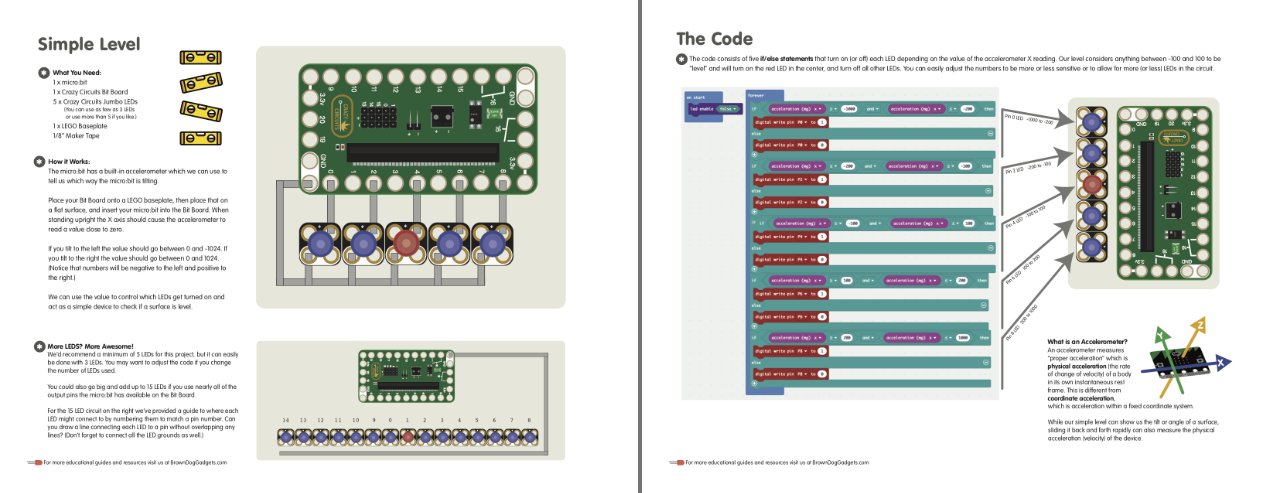
Here’s a super-easy micro:bit project that just uses a few Crazy Circuits LEDs, some Maker Tape, and a LEGO baseplate. It’s a Simple Level. Since the micro:bit has a built-in accelerometer we can easily check which way it is tilting just like an old fashioned level with liquid and an air bubble.

This project just uses five LEDs, but we outline how you could easily expand it to many more (and yes, we’ll probably build a larger one soon, as well as a multi-dimensional level.)

As always, there’s a diagram and more info as well as a look at the code. For each of these projects, if I can do a somewhat simple explanation of the code I think it’s helpful. You can certainly use the code and never dig into it, but I hope that people do. Kids (and adults) should learn to code if only for the fact that it can help understand how the world works, at least that’s how I view it.

Oh, I should mention that the Bit Board is now available via Kickstarter! And if crowdfunding isn’t your thing you can also get it direct from the Brown Dog Gadgets Shop.

Categories
Uncategorized

Meeting Controls

The latest fun project over at Brown Dog Gadgets is a USB device to toggle your microphone and camera on and off during video calls on your computer. Check out Meeting Controls!

We’ve got the “Business Edition” above for the adults with their serious work calls, as well as the “Fun Edition” for kids stuck in those all-day distance learning sessions.

This is a pretty simple build if you’ve got the right LEGO pieces laying around. (If you don’t a quick trip to BrickOwl.com will get you sorted straightaway.)

As always, you don’t have to perfectly replicate the LEGO build we’ve done, and it should be considered a starting point, or recommendation of one way to do it. That’s the beauty of LEGO building… it’s open ended. (Of course we do have a few tricks along the way.)

The Invention Board can be programming to work as a USB HID device, and we provide all the code you’ll need to work with Zoom, Google Meet, and even Microsoft Teams. (Webex didn’t work… blame their developers.)

Some nice touches, like the mic and camera icon, were added by using a vinyl cutter to make small stickers that are applied to flat LEGO bricks. Totally optional, but adds a bit of class and distinction to this very handy device.

As always, a wiring taping diagram and notes on the build are included in an eye-pleasing arrangement of words and images. Check out this project and more from Brown Dog Gadgets, especially if you’re an educator looking for a great invention & creativity platform that combines circuits with LEGO building.

[ Twitter Content Removed ]