Hello Friends, I’ve been publishing on the Internet for close to three decades now. In the early days there was this idea of having a “home” on the World Wide Web in the form of your own web site where you could say what you wanted to, and you could be in control of what you said. That idea went away when the WWW got popular and everyone joined and just signed up for LiveJournal, Myspace, Tumblr, Facebook, Twitter, or whatever the new thing is… Well, some of us did not give up on the idea. Welcome!
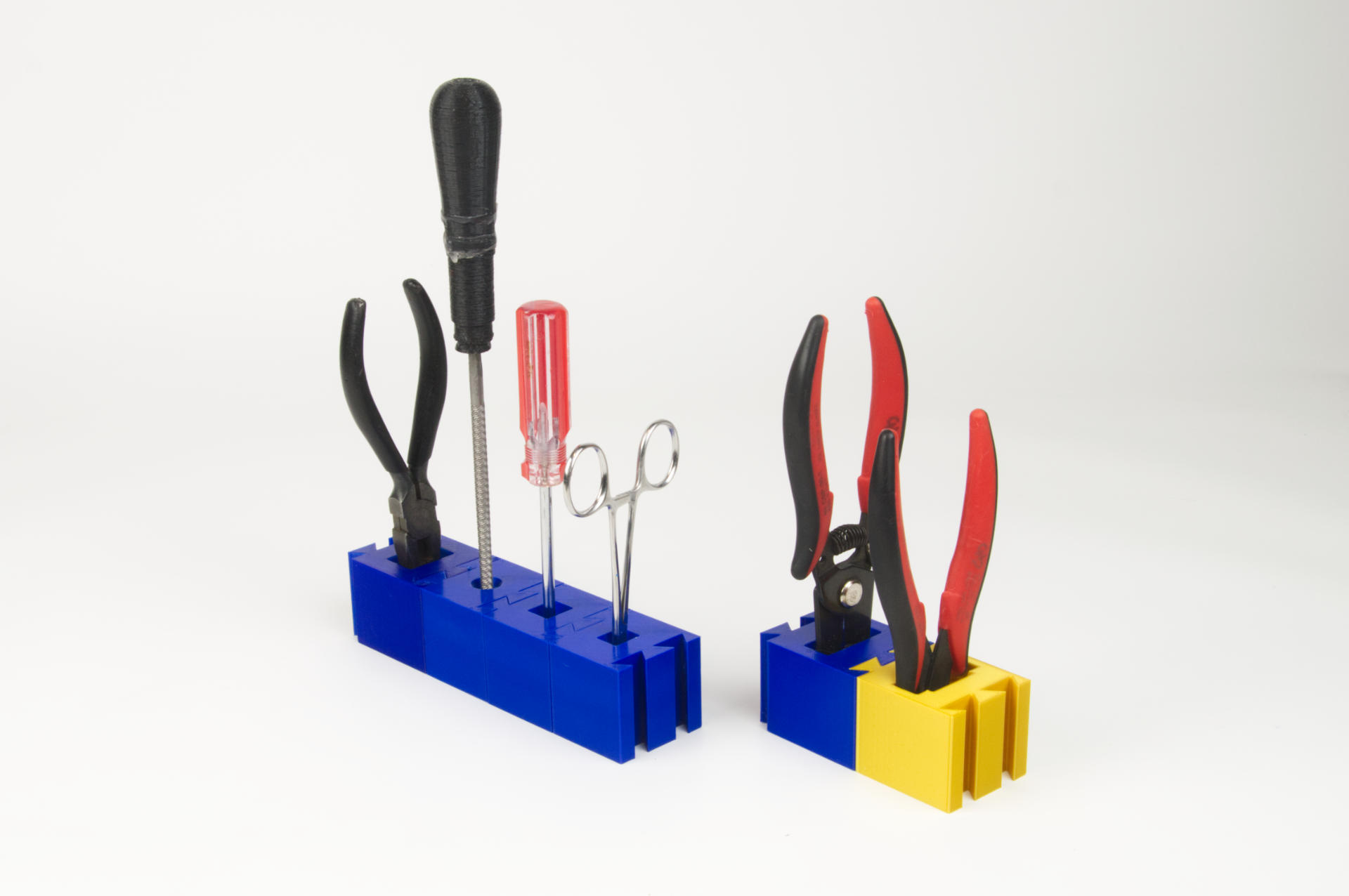
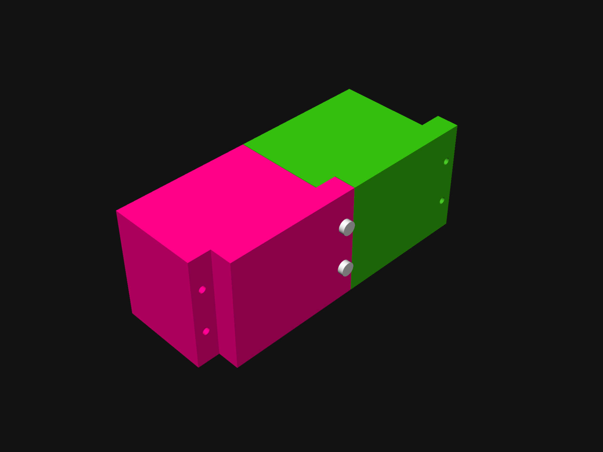
Recently Hackaday featured one of my posts in A Simple And Effective 3D Filament Splicer and while I’ve had my projects featured a number of times over the years, the results are not always positive. One of my projects ended up on Hackaday over a decade ago and some of the comments about me personally were quite cruel, which I did not care for… (Yes, Hackaday has got better over the years, but it’s still incredibly easy for people to make ridiculous comments.)
Anyway, with this recent post, and the idea that this is a site on the Internet I can control, I will now respond to the comments right here! Why? Because I can… This is the sort of thing you can do when you have a web site on the Internet.
And of course, there’s a reason people say “Don’t read the comments!” and in my experience it’s mainly because people who haven’t done a thing have all sorts of opinions on the thing you’ve done, even though they haven’t done it. Somehow they know why you’ve done it wrong, and they also know the right way to do it! It’s pretty amazing. (My original post Fusing 3D Printer Filament)
Cyna says:
No to the very first sentence.
First Comment! Thanks! Very helpful! If it’s not for you, feel free to move on.
DaveAZ says:
I’ve never had the need to do this. The printer itself works just fine, and offline splicing means that you have to wind the new section on to the old.
Hey DaveAZ, we all have different experiences and use cases. My experience is that I end up with things like samples from vendors, rolls with very little filament left, or other short pieces I want to combine into part of a spool. This method allows that, and works well for me.
GoguyT3d says:
Bear in mind that the filament on both ends must be essentially “melted” before fusing and even then a high chance of the joint snapping in the extruder or along bowden bends. I’ve done it many times from “end of spool” to beginning of next and using a candle 45° cut bowden to smooth the melted bulge and it’d still very hard to get the material to stay joined and your also risking blackened/burnt filament in the process from the flame. I just save the last 100g of a spool until I need to print something under that size. Too much work for very little success.
Dear GoguyT3d, you may have missed the part where I mention this method produces almost no bulge, no burnt filament, and (so far) good success. In the post I said “Give it a (light to medium) tug to make sure it doesn’t come apart. If it separates, cut the ends and try again.” I made a spool with about a dozen joints, printed a number of objects, and had zero issues. I will keep testing, but so far I’ve had good success.
Gregory Scott Pearce says:
I simply start a print when I have time to see the roll ending. Then let the printer use up the last foot or so while putting the next roll on. When the last little bit is going in, follow it with the new filament pushing it until the hob gear is completely in control (you will have retractions most likely just keep compression…) For all new ends I figured out this trick for better insertion: with very little contact heat end of filament about 1/2? from end… the quickly pull it out. Cut the filament at the start of the thinner section. Makes the end nicely tapered so as not total jam up.
That sounds more complex than my method, and requires you to watch the printer the entire time waiting for the filament to run out? I don’t have time for that because I have to go to work, and sleep, and do other things… If you have time to watch your prints though, that’s awesome! I remember watching a MakerBot Cupcake the whole time it printed an object back in 2012 and it was fascinating…
Greg A says:
heh, i actually want to do this, because i cut off about 30m of filament at a time to leave on the printer (so the whole spool is not soaking up basement humidity for months). i’ve gotten pretty good at pausing the print, switching to the next filament segment, and then continuing again…but i waste about a meter of filament within the bowden tube, and obviously i’d like to do it without pausing.
so this got my attention and i was trying to decide if i would actually try it. unfortunately, Pete came to my rescue to help with the decision…he helpfully pointed out that he usually has a spool at one end. and that’s my undoing…i have a big coil of 60 loops of filament at one end, and my 3d printer on the other end. there’s no ready way for me to slide the doohicky out of the way, unless i want to manually feed it around 60 loops of filament.
i guess i could leave it on the filament and it’ll just slide on its own once it runs into the inlet on my extruder assembly.
but i think i’ll give it a pass. oh well. it would be neat!
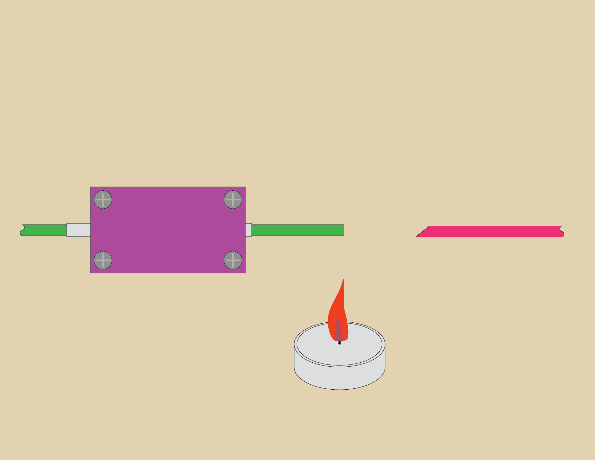
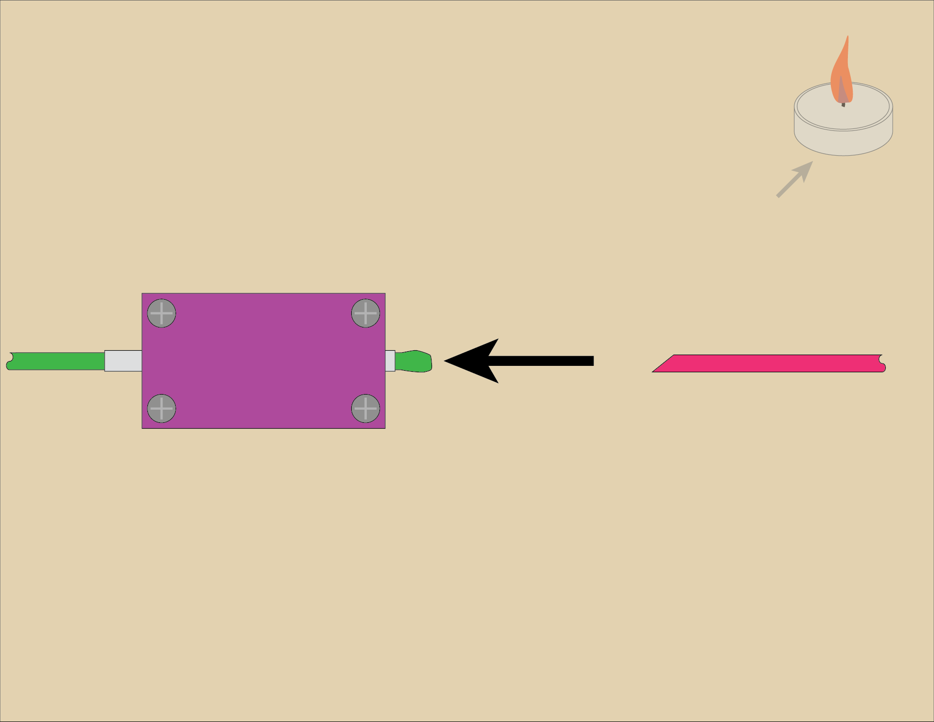
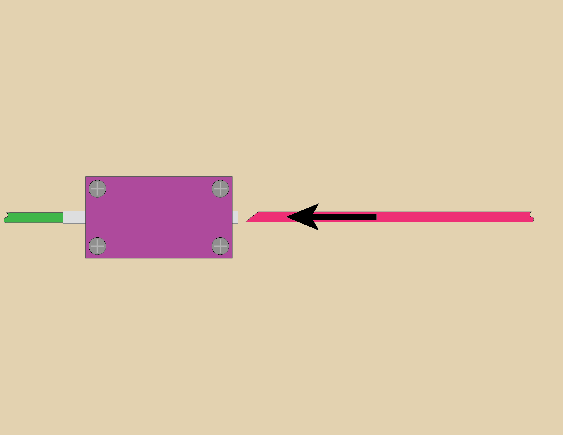
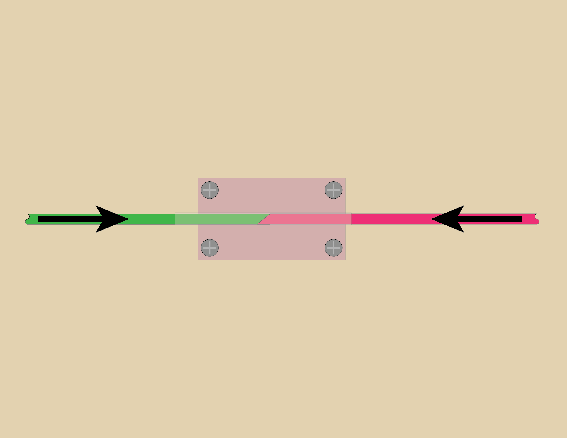
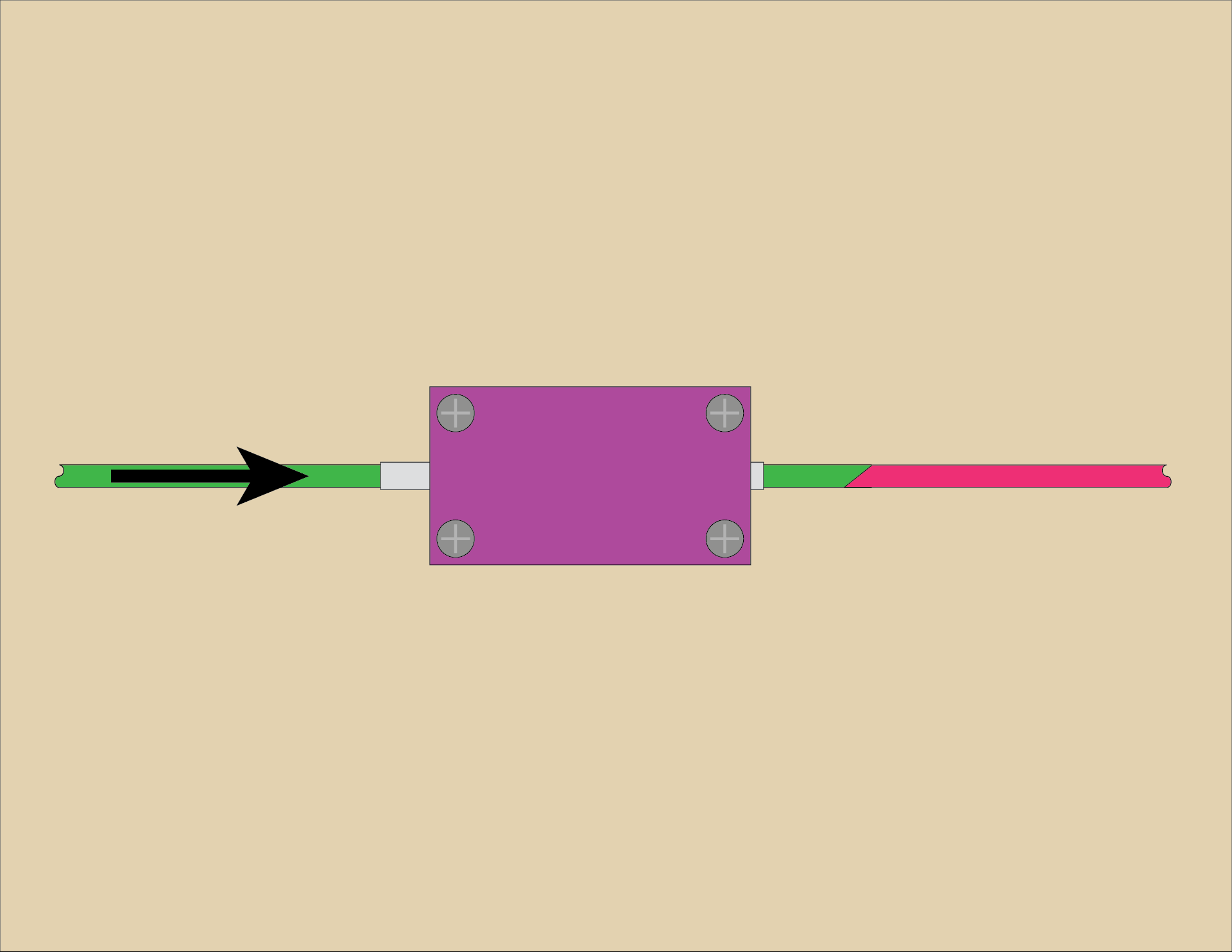
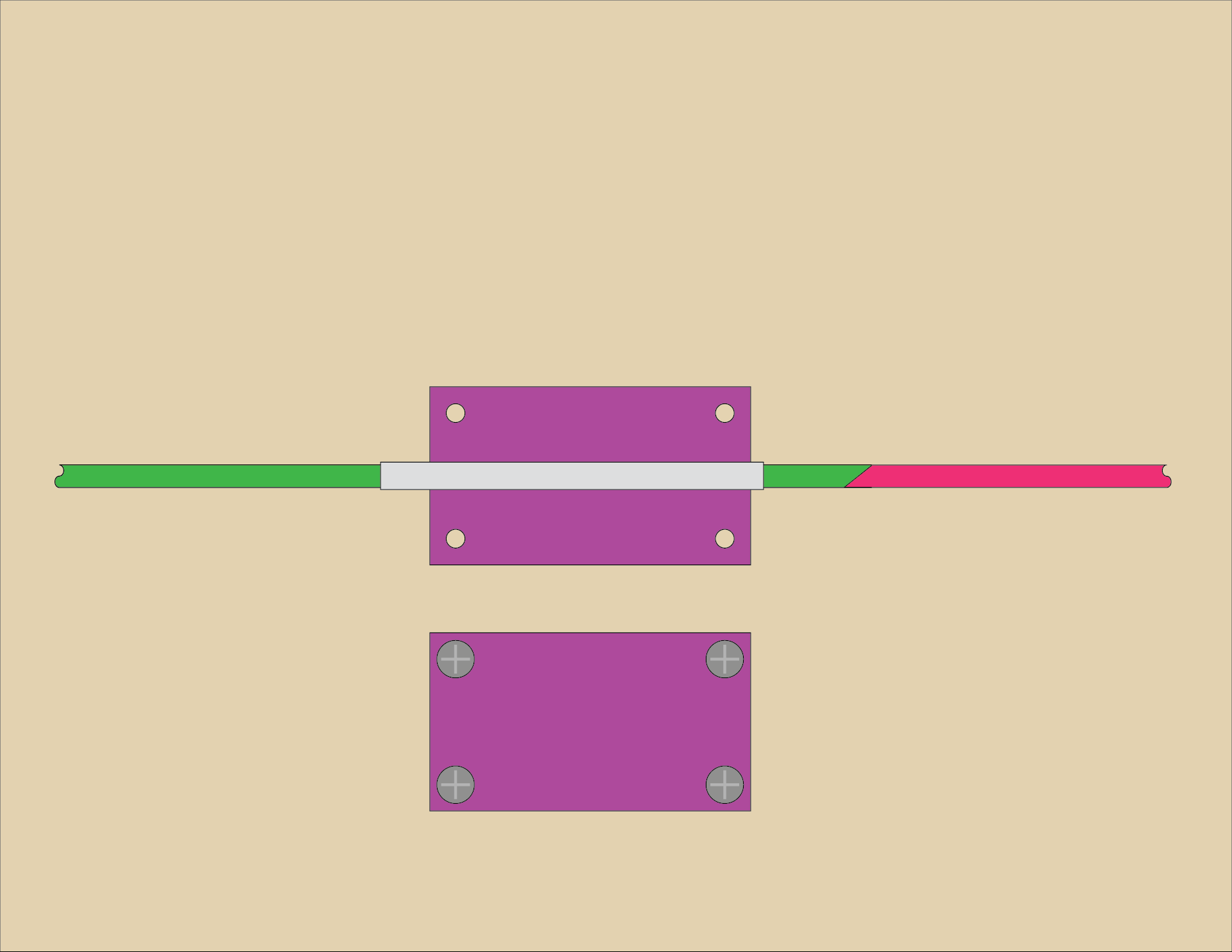
I’m not sure I get the issue Greg A is having. You make a splice, feed it through the tube, then add another piece (and another splice) and feed that through the tube, and you keep going. Is Greg A trying to do this inline while a spool is feeding to the printer during a print? This one just baffles me…
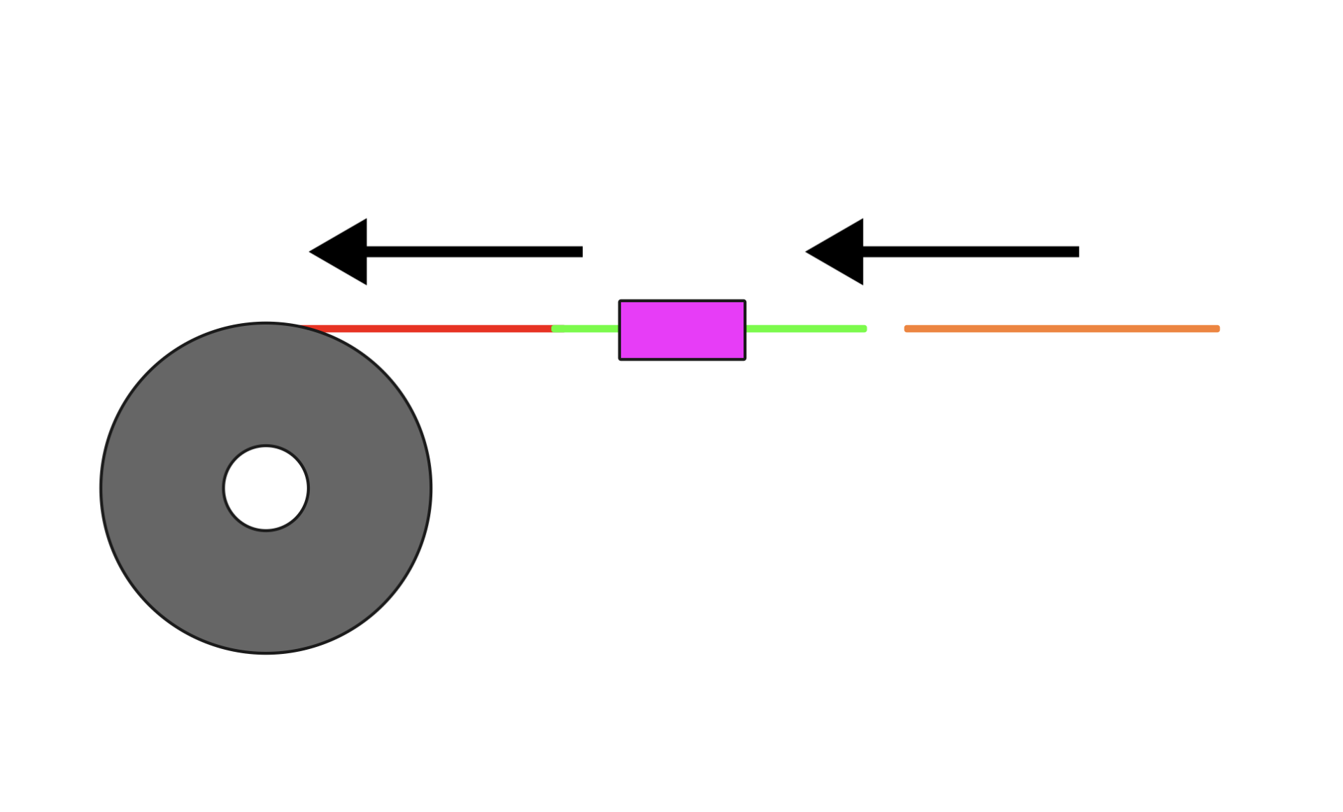
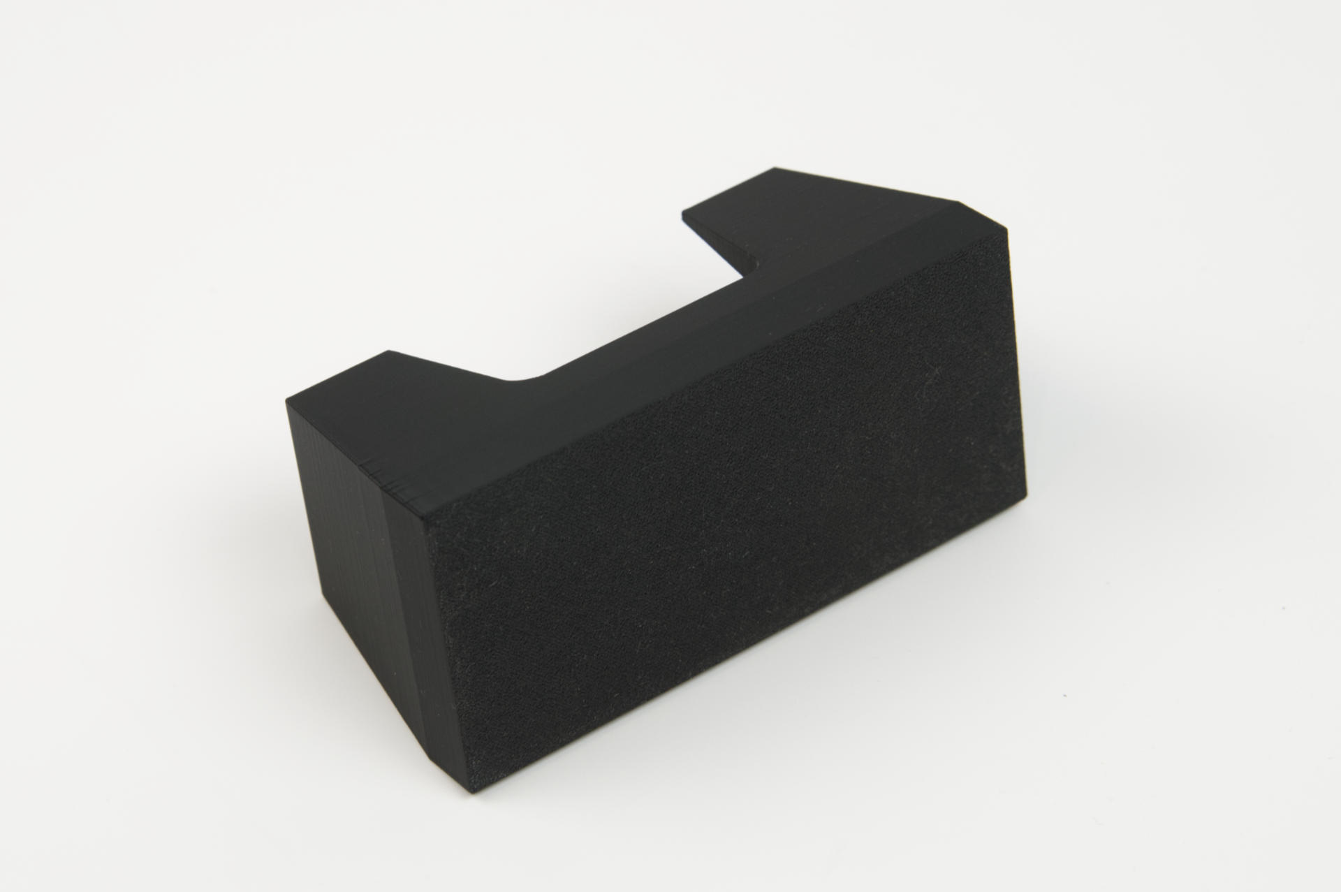
Does this diagram help?
Chris says:
It is a nice device, but there are certainly better executed examples of this. With a piece of tubing and a pen spring, you can 3d print the connector ring and just push the two pieces together.
Yes, I’ve seen this thing and I tried using a spring and it did not work for me, but the method I used did work for me. As I mentioned “find what works for you and go with that”. If the spring works for you, awesome! I have presented an alternative method that may work for others.
Isaac Horowitz says:
Why not just the buy a tool used to do this job? It’s called a belt splicer. You lock the pieces in the clamp, turn it on, it heats up, you squeeze the handle, it shoves the pieces together. Granted its for rubber belts, but it will melt our filaments. A little tweaking and we could make them work perfect for spool splicing.
I like how the “tool used to do this job” isn’t actually the “tool used to do this job”, which MinorHavoc pointed out. I do look forward to seeing the device Isaac Horowitz comes up with using a hacked belt splicer though!
Hans says:
I simply print until my Prusa tells me that it’s out of filament, insert the next filament and press continue…
I hope someday I have no need to work, sleep, or do other things and can just sit around watching printers print and waiting for them to tell me they need more filament… sigh.
Well that was fun! I don’t know that it was the best use of my time, but I needed to get some writing done today, so that should suffice.
I hope Hackaday takes no offense at this post. In case you are interested, RasterWeb! started 7 years before Hackaday launched, and has only had one owner during that time. ;)