When last we discussed rotary encoding, it was all experimental. Since the project (which will eventually be revealed) is complete, I figured I should share a bit more about the exploration and final solution.

I moved from printed paper disks to laser-cut disks. I cut some 3mm Baltic Birch plywood at Milwaukee Makerspace. They worked well, but since I was hoping to get more steps/resolution I continued with the paper prototypes as well.
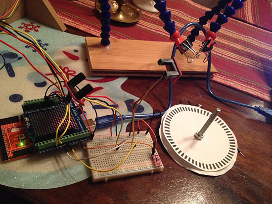
The one in the photo above was a bit too fine… too many steps. The more steps the more precise the alignment has to be, and the more chance of errors.

We had some concerns about a disk spinning between a U-shaped sensor with just a few millimeters on each side, so rather than just go with the GP1A57HRJ00F Photo Interrupter, I started experimenting with the QRD1114 Optical Detector / Phototransistor as an alternative.

The idea would be to use a wider disk and instead of it spinning between two pieces, it would have the encoding stripe on the edge, and the sensors would be on the outside of the disk. Back to the breadboard! The QRD1114s require a pair of resistors to work properly, so I wired it up and did a few tests and things seemed to work.

My first tests just involved sliding a piece of striped paper across the sensors, but I needed a real disk. I used the laser cutter at Brown Dog Gadgets to cut some disks from 1″ pink foam, and also from 1/4″ foamcore board. The pink foam actually ended up with concave sides due to the melting power of the laser, so I used the foamcore board pieces stacked up.

Math time! How long of a strip do we need to wrap around the disk? Well, you can determine the circumference of a circle if you know the radius or diameter. Hooray for math! Above is a letter size file that I could print on a laser printer to produce the stripes I needed. The thin line on the right side was used for alignment since I had to use multiple stripes to wrap around the disk.

Here’s a sneak peek of what the final disk looks like. There’s a few more steps before we got this far though, so I’ll continue the story next time.
1 reply on “More Rotary Encoding”
If you need more pulses per rev, use multiple sensors and set them so they are phase-wise a fraction of the stripe width apart.