Categories
Uncategorized

Enclosure Prototyping

I’ve made a lot of laser cut enclosures over the years. I typically make them out of 3mm or 6mm Baltic Birch plywood, and sometimes I even mix the two sizes, which is fun because you need to remember which tabs need 3mm and which need 6mm.

As much as I’ve made a lot of enclosures, I still occasionally screw up, or get things not quite right the first time. Typically I design the entire enclosure in software and then cut things out. If I’m smart I’ll first cut it using cardboard to prototype how it all goes together. Cardboard isn’t always the correct thickness, but it can often get you close enough and reveal flaws in your design that you can correct before you start cutting wood.

One of my recent discoveries is that if your cardboard is too thick you can squish it in the hydraulic press and it’ll stay pretty squished. There’s a little bounce back, but it’ll be thinner than it was originally.

Categories
Uncategorized

Printed Circuit Boards from JLCPCB

jlcpcb-website

Musical maniac Hal over at Milwaukee Makerspace told me about JLCPCB and suggested I try them out. Since I had a coupon due to signing up as a new customer, I ordered 100 boards and chose the free shipping option. The boards were ordered on July 21st and as of August 8th I’m still waiting for them. Since I’m getting 100 printed circuit boards for about 13 cents a piece, I’m okay waiting for them!)

friting-pcb

Meanwhile, I had a project at work where I was trying to decide how to wire something and not create a messy rat’s nest of wires, so I decided a PCB would be the best solution. I whipped up a simple board in Fritzing (Yeah, I know… Fritzing is “garbage” except I know how to use it, can use it very fast, and it’s fine for simple boards.)

pcb-traces

One tricky thing with this board was that the traces had to be pretty thin to route around the solder pads. I exported the files as SVGs and took a look, and it seemed good. Since I needed these for a work project, and I needed them fast, I chose the expensive shipping option. The 5 PCBs were $2.00 and the shipping via DHL was $16.81, so in total it was $18.81 for 5 boards that I got in about 4 days! Seriously… I uploaded the files on July 25th at 04:40 (GMT+8) and got them delivered July 29th at 14:31 (GMT-5).

mux-epander-pcb

The first thing I did was pull out a meter to check all the traces… all good! The board looks great. I soldered header pins into three rows and now I need to solder 48 wires onto it. Wheeeee! (Oh yeah, the board is plugged into a Mux Shield II.)

Categories
Uncategorized

Prototyping a bunch of knobs…

knob-rot

If you’ve ever used a potentiometer you know it can only turn so far. About 270 degrees of rotation is what you get out of most potentiometers, which is plenty. The problem with using potentiometers in museum exhibits is that while adults (typically) know that when the knob stops turning you should stop turning the knob, kids don’t always know this. Kids are notorious for going too far when it comes to physical controls.

pieces-stacked

So I’ve been working on a way to use potentiometers in an exhibit, but hide them down below in the cabinet, and expose a control knob to the surface that has limited rotation. About 220 degrees of rotation. I could do more, but the idea of using less than 270 is the key. If we don’t get too close to the beginning or end of the rotation limit, we should be able to prevent the potentiometer from being twisted too far and becoming damaged.

pieces-all

I drew up the parts needed to build an encased knob with a hard stop inside. In the final version the knob will be machined from HDPE plastic using a CNC router. I opted to 3D print the pieces for the prototype because it was quick and easy. (“Quick” is relative, of course, but I finished up the drawing and got the model printing at the end of the day, so the printer did the work overnight while I wasn’t there.)

pieces-3d

I drew all the pieces in Inkscape and then exported DXF files and brought them into OpenSCAD and extruded them to 1/4″ high. There’s a 1/4″ hole in a few pieces (and a slightly larger hole in the bottom piece) so that a 1/4″ steel shaft can be inserted. The shaft will be connected to the potentiometer. (I made a 3D printed prototype of that too, which you can see here and here.)

pieces-exploded

Here’s an exploded view of the assembly. Sometimes it’s tricky to design things like this using flat 2D shapes in Inkscape, but I’ve gotten used to it, and I think I’m pretty good at it. I should mention I also printed a paper prototype to help figure things out along the way. (And yes, the original plan was to laser cut the pieces out of foam core which would have made the most sense, but the laser cutter was not available when I did this.) The fact that I created 3D models did allow me to make the nice exploded view very easily.

pieces-stacked-orange

Here’s a quick assembly using hot glue. Just to test how it worked, as well as get a feel for the size of it. (I’ll have a follow-up post about the layout of the whole panel.)

knob-together

HDPE can’t really be glued, so we use screws (hidden when possible) to attach layers. We may be able to get away with fewer layers than I used here, because I used 1/4″ layers, but it might make sense to use 1/2″ or 3/4″ layers since we often get HDPE in those thicknesses. And of course we can pocket things out, and not just use a flat stack. (Again, this is a prototype.)

Categories
Uncategorized

More Rotary Encoding

When last we discussed rotary encoding, it was all experimental. Since the project (which will eventually be revealed) is complete, I figured I should share a bit more about the exploration and final solution.

Encoding Disk

I moved from printed paper disks to laser-cut disks. I cut some 3mm Baltic Birch plywood at Milwaukee Makerspace. They worked well, but since I was hoping to get more steps/resolution I continued with the paper prototypes as well.

Encoding Disk

The one in the photo above was a bit too fine… too many steps. The more steps the more precise the alignment has to be, and the more chance of errors.

Gap

We had some concerns about a disk spinning between a U-shaped sensor with just a few millimeters on each side, so rather than just go with the GP1A57HRJ00F Photo Interrupter, I started experimenting with the QRD1114 Optical Detector / Phototransistor as an alternative.

Sensors

The idea would be to use a wider disk and instead of it spinning between two pieces, it would have the encoding stripe on the edge, and the sensors would be on the outside of the disk. Back to the breadboard! The QRD1114s require a pair of resistors to work properly, so I wired it up and did a few tests and things seemed to work.

Encoding Strips

My first tests just involved sliding a piece of striped paper across the sensors, but I needed a real disk. I used the laser cutter at Brown Dog Gadgets to cut some disks from 1″ pink foam, and also from 1/4″ foamcore board. The pink foam actually ended up with concave sides due to the melting power of the laser, so I used the foamcore board pieces stacked up.

Stripes

Math time! How long of a strip do we need to wrap around the disk? Well, you can determine the circumference of a circle if you know the radius or diameter. Hooray for math! Above is a letter size file that I could print on a laser printer to produce the stripes I needed. The thin line on the right side was used for alignment since I had to use multiple stripes to wrap around the disk.

Encoder

Here’s a sneak peek of what the final disk looks like. There’s a few more steps before we got this far though, so I’ll continue the story next time.

Categories
Uncategorized

3rD Times The Charm!

Three Motor Holders

While I usually describe 3D printing to people with something like “you can make beautiful things that are art, or functional things like parts” I’ve been printing a lot of parts lately (thought I still print pretty things!)

The parts I’m printing are of my design, for things I am building, and they often have to fit existing real-world objects. The process usually involves measure thing with calipers to get dimensions, and then designing things in 3D software. (I’m leaning more towards OpenSCAD latley, as opposed to Sketchup.)

If you’re just downloading and printing objects from Thingverse, they’ll (hopefully) work on the first try, but if you’re doing everything on your own, it may take a few tries.

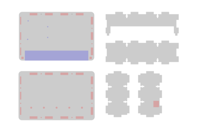
I wanted to print a small motor mount for this DC motor that Adafruit sells. So I got out the calipers and went to work.

Motor in the second holder

For the first attempt (see top photo) I completely screwed up by using the inside dimensions (where the motor should fit) as the outside dimensions. Stupid mistake! On my second attempt I got it right, and the motor fit almost perfectly.

Motor in third holder

On the third iteration I made minor adjustments to the outer walls, and I also added an “air hole” on the top. The motor has two slots in the body which I assume draw air into it to prevent overheating. (You can see I know very little about motor design right now.)

Motor and holder

Back in June when the guys from MakerBot stopped by Milwaukee Makerspace, I talked to Skimbal, and asked how many revisions he went through when designing things, and he said about two or three. I was impressed by this because last year I tried designing a real-word replacement part and I think I made about ten versions of it. Of course part of this was my lack of 3D skills, and part of it may have been issues with the old CupCake I was using.

Motor in the holder

So I’m pretty happy with the fact that I can get a good version of a part in just a few tries now. (Though I should admit that I’m not happy with the slots for the screws, and may end up tweaking things a bit more, which is pretty darn easy in OpenSCAD.)

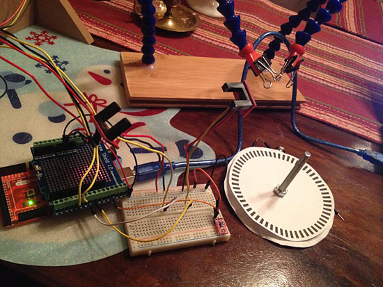
When I was talking to someone about 3D printers this summer, they didn’t see the point of having one at home when there were so many companies that allowed you to upload a design and would print it and ship it to you. Here’s where a home 3D printer shines; I can measure a part, get a prototype printed, test it, and print another version all in a single afternoon. Now that’s rapid prototyping!

And a mirror holder!

Oh yeah, I also printed a mirror holder. It took just two revisions to get one that worked well.