In my last RepRap post I had modified the design to be much wider in the x and y planes, and as I did that I started to realized that it would cause a number of issues with the build. I mainly did this because I have plenty of Aluminum extrusion to work with, but as I thought about it more I started to remember why 3D printers are mostly the size that they are.
When you go beyond the typical build envelope of most 3D printers things get complicated. You can’t use 8mm rods because they’ll sag under the weight they carry, and if you make them long enough they’ll even sag under their own weight, so you need to start using other methods of linear motion. I thought about following some of Mark’s lessons from SoM, but things get expensive when you start doing that. (He does manage to scrounge and buy used things, but that can be tricky as well.)
I will definitely follow some of Mark’s techniques though. For instance, look at this build for the BA3DP. Start counting the amount of hardware used for those corner plates. Crazy! The Mark Method is to tap the (milled square) extrusion and screw it together. Simple! And you can always add some corner brackets if you want, but they aren’t as necessary and definitely don’t need as many nuts and bolts.
Some printer designs use T-slot frame members joined together with printed plastic parts. Avoid the temptation to do that. If you want rigidity, you have to bolt/weld metal to metal. T-slot extrusions are designed to accommodate standard sized screws. All you have to do to join two pieces is drill one hole and tap the end hole to receive the screw. Likewise, attaching things to the T-slot can be done by using nuts designed to fit the slots (or by making your own).
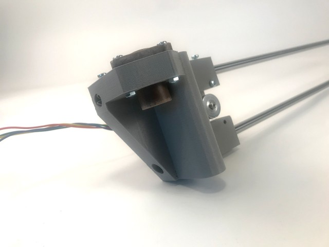
That’s my plan for assembling a rigid square frame using 40mm Aluminum extrusion. Speaking of the extrusion, here’s a test fit for some of the printed parts. I’ll probably start with these and tweak if needed. Mark suggested I make the motor mounts from square Aluminum tube, and that might be a future upgrade, but I’m okay to start with some printed parts. I do want to try to reuse many parts from my old RepRap, and use parts I have on hand, so I’m going to try to stick to that plan.

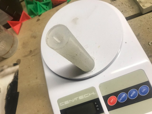
One thing I don’t have is 12mm linear bearings for my y axis. I’m going to try igus drylin linear bearings. I’ll need to make mounts for them that compress them a bit so they fit properly. I’ve read enough to know you can’t just zip tie them into place, (To be honest, wires are the only things I plan to zip tie into place.)
I still need to shop for hardware. Either 5/16″ or 8mm bolts, depending on what I’m ordering from BoltDepot or buying locally in the coming weeks.

One thing I’m still not totally sure of is where the vertical pieces of the gantry will sit yet. I’ve tried to calculate where to place it so that the extruder will reach the front and back of the bed properly, but I still don’t have that nailed down… partly because I’m still not sure how the x axis and carriage will work as far as mounting the hot end, connecting to the smooth rods and lead screws… I also want the carriage to be easily removable, and possibly replaceable with, another end effector. :)

Since I’m going to avoid going wider than I need to for this printer, I can get away with 8mm rods for the x axis like I did with my old RepRap. I’ll probably sacrifice a little rigidity and precision, but that’s a price I’m willing to pay right now to avoid paying more for a proper linear guide on a square Aluminum tube. (Future upgrade?)
I’d like to keep the x axis motor within the envelope of the machine, and not hang it outside as many printers do, but I’ll need to design that as I’ve not found a solution yet that fits what I want. Time for more CAD work I guess.