The Reflect-O-Scope was an interactive museum exhibit I worked on a few years ago. It was a fantastical machine that allows users (typically children) to slide materials under a microscope and examine them. The materials were from the sponsor of the exhibit and consisted of specialty tape materials adhered to plastic boards.
One of the original ideas was to allow for focusing, but that got scrapped. We figured kids would put almost anything under a microscope, their hand, their little sister, etc. Focusing meant a moving mechanism, and it was deemed to complex at the time.
The sculptural build was done by John McGeen and Austin Boechler. My focus was on the hardware and software. There’s a USB microscope connected to a computer and then a small HDMI display in the “goggle” shaped piece that the user looks into. It’s all a bit “periscope” like in design.
The original design also had a secondary monitor (a large TV) that would be mounted further away, so people could see weird things on the TV and it would draw them over. Lots of features got killed due to lack of time or other reasons. Most of what you see on a museum floor probably started out a lot more complex when originally designed, and then simplified as time goes on.
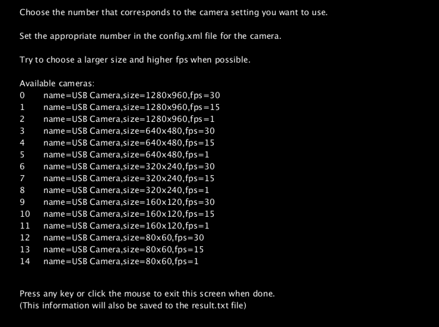
I wrote the software, which is just an application written in Processing that automagically launches at boot up, runs full screen, and shows the output from the USB microscope. There’s also a companion application called “List Cameras” that can display all the connected USB cameras and all of the possible resolutions they support. This is there in case the USB microscope ever needs to get replace. The exhibit tech just needs to run the application and then edit a config file. No recompiling of the application is necessary.
One more fun addition was a white plastic tube running along the outside with some NeoPixels in it featuring some funky color runs to add to the fantastical nature of the piece.
One of the nice things about this component was that the software was created in-house, so the component could be replicated easily without additional license fees. (We had an amazing software partner we used for the complex things, but simple stuff was done, when possible, in-house by the tech team, which was basically me.)
For my part, I handled the technology that went into the exhibit. (Which sadly, you can’t see much of in these photos because some were shot after things were powered down.) For three of the five components, I spec’d the hardware and worked with a software developer to upgrade the old version of the software to something more modern, stable, and easier to calibrate and support.
I can’t even tell you how many golf balls I rolled down all of those ramps. At one point we had an issue with a projector overheating and I set up a time lapse camera to run all day and overnight to give us some idea how long it was staying on before shutting off. We eventually fixed it by adding a duct to the projector housing to draw the heat out and away. We’ve used earlier models of this projector with no issue, but this is why we do extensive testing… you never know what problems are going to pop up.
If this exhibit looks familiar (!?) it might be because there are now three copies/versions of it. Besides this one which was a “for sale” item, we’ve got two on the road, one of which will be returning to the Betty Brinn Museum this summer.
By the way, if you occasionally have a bunch of old golf balls you want to get rid of, let me know… There’s a non-profit in Milwaukee who would love to take them off your hands. ;)
In the interest of not waiting too long after I build something to share it here, I’m going to drop a bunch of random info into this post, knowing that it may not be well written or cohesive, but I’ve decided that’s okay…
Logo is an educational programming language known for its use of turtle graphics. Commands for movement produce drawings on a screen that teach students to understand, predict and think about the turtle’s motion by imagining what they would do if they were the turtle.
And finally, if you’re not familiar with Brinn Labs (where this was created) we are were the exhibit development group of a children’s museum, and we make made safe, durable, fun, educational exhibits for museums and other institutions, mostly aimed at early learners.
Here’s the original concept I shared with the team. Things always change during the development process, but this is still pretty close to what we came up with.
In designing the physical board and pieces, I took inspiration from the block interface used by Scratch. In Scratch pieces fit together to help you figure out where things go, and color also help denote function.
Here’s a mock-up of the board where the pieces will go. The board has pockets that the pieces fit into, and in each pocket is a sensor that reads the back of the piece. Note that the pieces only fit into the pocket that matches the function. You can’t put a direction piece into the color pocket. The pieces also cannot fit in backwards or be rotated in the wrong direction. Designing this to work took some time, and it’s all there to help you get it right.
The right side shows the indent for the loop code, as well as the use of parens that many programming languages use. Note that the loop pieces are not required, but if you put in the beginning loop statement and not the end loop statement (or vice versa) you’ll get an error.
We’re using the QTR-8RC Reflectance Sensor Array boards from Pololu. Each pocket has one sensor board to read the barcode on the back of the pieces. The barcode allows us to use a binary code for each piece. This means no technology is embedded into the pieces, and they’re (fairly) cheap and easy to replace as needed.
Here’s a look at the print file for some of the pieces, showing the back. You can also (faintly) see the cut lines for the pieces.
Here’s a portion of the binary code for some of the pieces. We actually doubled it up as a sort of checksum to make sure things were read right.
Each sensor is mounted from the back of the panel with a 3D printed mount that sets it right below the surface. We found a gray filament that was a pretty close match to the gray HDPE we used for the front panel. The top part of the sensor mount matches the holes milled into the HDPE by the CNC router, and includes the radius of a 1/4″ router bit.
My favorite part about 3D printing the sensor mounts is that you can set the height of the part where the screws go to match the screws you use and the material you are screwing into so they go in the exact distance you want, and not too far. No screws poking through material, and no screws not inserted enough to get a good hold.
We couldn’t leave the sensors exposed, so we laser cut clear acrylic pieces to place into the pockets. Hopefully they’ll stand up to the abuse they’ll get, but if they get too scratched or worn, it’s easy to swap in a new one. (If you’re keep track, we’ve used a 3D printer, laser cutter, and CNC machine so far…)
Here’s a look at a mock-up of the pieces. This is an early iteration but shows some of the color choices as well as all the pieces together.
I’m not showing you the inside of the cabinet, but all of the sensors connect to a microcontroller that is connected to a computer. The microcontroller reads the sensors, determines which pieces are in which pockets, and reads the button presses to run the code on the computer and reset things.
To program the turtle, you put the pieces in the tray, and press “Run”. If you get an error it will show on screen and also blink an LED on the board for the “line” where the error is. Once you correct your error(s) you can hit “Run” again and watch your code execute. You can run over and over until you want to clear the screen by pressing the “Reset” button, which clears things and sends the turtle back home.
We didn’t implement pen up/pen down, because this is a simplified version meant for young children/early learners. I think that as far as a STEM component it turned out well, and creating it allowed me to combine my love of computers, programming, turtles, Logo, and design into something awesome.
I hope Seymour Papert would be proud of this. If you’re not familiar with his work, he’s been considered the world’s foremost expert on how technology can provide new ways to learn and teach mathematics, thinking in general, and other subjects.
People laughed at Seymour Papert in the 1960s, more than half a century ago, when he vividly talked about children using computers as instruments for learning and for enhancing creativity, innovation, and “concretizing” computational thinking.
Here’s some kids having a good time learning about coding!
On the durability scale it goes from “Consumer” to “Commercial” to “Industrial” and then finally to “Children’s Museum”.
While most adults can figured out how things work, and most will actually use things the way they are designed to work, children will use things every way possible, not (usually) maliciously, but because the are still figuring things out. Install a lever that goes up and down, and they’ll move it up and down with all the force their small bodies can muster, so you might want to add some hard stops on the inside.
Kids also can’t read/don’t read (to be fair, many adults don’t read either) so add some arrows showing direction of movement. Also if those arrows are just vinyl you applied to the surface, they’ll get peeled off. Every interaction needs to be thought about in great detail, and sometimes you need to think like an angry vandal hell-bent on destroying things.
Plan for things to break, because they will, but make them easy to maintain and repair. Use off-the-shelf parts when you can, so replacements are easy, or if you fabricate the parts yourself, make spares, and document how to make more spares in the future. Use Loctite. Use set screws. Use Loctite on set screws. Use hot glue. Use lots of hot glue. Use screws and bolts, not nails and staples. Make sure you can take it apart and repair it.
I recently repaired the traffic and walk signals at BBCM. The system had been running on a PLC (Programmable Logic Controller) which failed, and rather than find the proprietary programming cable and find and install the PLC Windows software, I decided to just put an Arduino and relay control board in place.
I had a Teensy++ 2.0 I had pulled from another exhibit during an upgrade, and an 8 channel relay board on hand. These relay boards come in different configurations from 1, 2, 4, 8, and even 16 relays. Since I really only needed 5 relays (and 5 pins) I could have used an ATtiny85, but I had the Teensy++ 2.0 readily available. The wiring is all done using female to female jumper wires.
I mounted everything to a piece of scrap MDF and added mounting holes to that, with the idea that we’d screw the whole thing directly into the wall. The relay board has mounting holes, but the Teensy does not. That’s probably my one complaint about the Teensy boards, is that mounting them isn’t always easy. My Teensy BOB has mounting holes, but for mounting this Teensy++ 2.0 I just used some 3M™ VHB™ tape. (The “VHB” stands for “Very High Bond”). And yes, there are a few 3D printed parts on there. At some point I should make a 3D printed holder/mount for a Teensy++ 2.0
I try to label things clearly. If I look at this thing in 6 months, or 2 years, or someone else has to look at it, I want it to be somewhat apparent what is what, so there’s not a lot of guesswork as to what is going on. I included a label with the name of the Arduino sketch, and I always like to label power supplies. Sometimes we use 5 volts, and sometimes 12 volts, and they typically have tiny hard to read type printed on the side of the power supply that you can’t see when it’s plugged in.
The one thing I should start to add to the labels is the URL of the wiki page where the thing is documented. (Next time I’ll do this.)
Here’s the controller mounted. It’s not pretty. We ended up re-using the mount that the PLC was in, rather than screwing it right into the wall. In my defense, we did this repair on the floor during open hours, and it’s mounted high on a wall behind a TV. Does it work? Yes… Is it awesome, no… but again, it totally works.
The wiring for the lights was all 12 VDC, not 110 VAC, so those thin gauge wires are fine. Also, they were labeled, which was handy. (Thanks previous person who worked on this and labeled things!)
I try to create wiring diagrams for everything. I use Fritzing because it’s simple and awesome and open and free. I often don’t find the components I need, but you can always just use a note and some text.
Here’s the script/sequence for the lights:
Green Light is ON
Walk Light is ON
Waiting 4 seconds…
Walk Light is OFF
Don’t Walk Light is BLINKING (for 5 seconds)
Green Light is OFF
Don’t Walk Light is ON
Yellow Light is ON
Waiting 4 seconds…
Yellow Light is OFF
Red Light is ON
Waiting 6 seconds…
Red Light is OFF
Don’t Walk Light is OFF
(Repeat sequence)
I wrote this up to figure out how to program things. I find it helpful to plan things out before I start writing the code.
At first I just talked through the light sequence with someone and we made some assumptions about how it worked. We were slightly wrong, which I discovered when I dug a bit deeper into traffic lights and walk signals. I read at least some of the (very long) Wikipedia page on Traffic Lights. I also hunted for other info, and found some on the Signals FAQ page on the Minnesota Department of Transportation web site. (As I mentioned with the 911 Phone I really do aim for an accurate and realistic experience with these things.)
It’s been a few weeks and the lights have been working fine. Hopefully that will continue to be the case. If something does stop working we’ll open a ticket for it so we have a record. And yes, we do use an issue tracker for our museum exhibits… doesn’t everyone?