Categories
Uncategorized

Laser Cutter Air Assist

My laser cutter has an air assist, which is really just a small air pump that runs when I am cutting or etching with the laser. The nice thing about LightBurn is that it adds the commands M106 and M107 to the start and end of each job so it will automatically trigger a pin on the Cohesion3D control board so that it can turn on and turn off the air assist.

Disclaimer: I’ve done a lot of projects using AC power controlled by relays using an Arduino or Raspberry Pi, and I’m comfortable working with 110VAC, but if you are not, I’d recommend you just get an Enclosed AC Relay System. It’s basically a power strip that can be controlled with two low voltage wires. Quick, easy, and safe.

Onto the project! Above you’ll see two parts loaded into LightBurn ready to cut. I tend to design my own enclosures rather than use any of the online generators, because I’m weird like that, and I enjoy it. You’ll notice the small part is only one piece, so I cut four of them, and they go on the sides. The top piece (to hold the outlet) I just cut another one, without the red parts getting cut, and I’ve got the bottom.

Hey look! All the parts cut from 3mm Baltic birch. Besides the holes for the AC socket I didn’t bother to add any other holes for wires, etc… I’ll just knock those out a with drill and/or file.

But first, we gotta glue things up… and to hold things together, why bother with clamps if I can just tape it up. (Rubber bands would also work. This is small, thin, lightweight wood.)

Basically, add glue… let that glue dry, add more glue. It’s just got to hold together when it’s all done…

Jam the electronics in there. The socket gets held in like a socket does, thanks to the holes on the top. For the relay board I typically use #4 screws to screw it down, though 3mm is a little thin, so I just glued a piece of scrap 3mm in place so I could screw into it and into the top piece a bit if needed… Oh look, I did add some corner supports.

You’ll also notice the wires leading into the enclosure. I probably just drilled holes and ran a round file across them until the wires seemed to fit so I could put the bottom piece on. Quick… and… Dirty!

Boom. Don’t even bother with screws or magnets or other fasteners for this thing… just add some black gaff tape to hold the bottom in place and we’re good.

Wires? Yeah, there’s a bunch of Dupont connectors going to the relay board. We need 5V, GND, and Signal. Simple. That’s all you need to trigger the relay. No microcontroller needed. The Dupont connectors plug into another set of Dupont connectors to change the gender (because I couldn’t find the right kind) and then into some Wago connectors. (Those things are nice!) From there I think I cut up and old 4 wire phone cable. Snip goes the RJ11 connectors!

Here’s the top, it looks not completely terrible, and prevents me from shocking myself with 110VAC, so that’s good.

Hey look, it works! You’ll see a weird switch on the top that the air assist pump plugs into. It’s just an illuminated on/off socket switch I had in the shop and used to confirm that the thing worked properly. I’ve probably removed it by now and put it on my workbench where it’s buried under three other unfinished projects.

Also worth noting: Laser cutting things for your laser cutter is akin to 3D printing things for your 3D printer.

Categories
Uncategorized

FSL Focus Device

I designed and printed a simple focusing device for my Full Spectrum MLE-40 4th Gen Hobby Laser Cutter. You can find it at FSL Focus Device on PrusaPrinters.org

The manual for the laser cutter shows a focus device cut from 3mm acrylic, which I originally used, but a thin piece of plastic isn’t really easy to stand up at 90 degrees properly (and won’t stand up on its own) so you couldn’t really tell if the focus was correct.

So instead I designed a triangular piece that could stand at 90 degrees much more easily. I chose a triangular shape rather than cylindrical or a rectangular cuboid so that I could easily slide one point of the triangular shape under the lip of the laser head.

Right now when it’s not in use it is stuck to the top of the laser cutter using some tape, but I’ve considered making a new version with embedded magnets so I can ditch the tape and stick it anywhere to the body of the machine.

Categories
Uncategorized

Laser Cutter Update

If you read my previous posts about my laser cutter, you may have been wondering what the latest progress is on it. Well, here’s an update!

First, some history… Brent bought this laser cutter back in 2012 (I think) then sold it to Jason in 2013. Jason kept it at Milwaukee Makerspace for about a year and a half and then took it home. He used it until he got a Glowforge in 2017 and then I got it from him. It took me at least six months before I really had it operational, but since it’s 2020 now I figured I should offer an update.

It’s been at my house and cutting things since late summer 2018, but it wasn’t really optimal. I am not 100% sure but I think it was all pretty much original parts. It would cut okay, but you had to go slow… really slow. Like, way too slow. I could do 3mm Baltic Birch, but had to go so slow for 6mm that it was basically a fire waiting to happen. The lens looked good to me, but I figured that lenses are cheap, so I started there. I got a Cloudray Lens (Diameter 18mm/Focal Length 50.8mm) and dropped it in place. (And yes, I do clean the mirrors and lens occasionally, and there is air assist running.)

I didn’t see vast improvements from the new lens, so I figured that if this was the original tube from 2012 or so, it was old, and probably needed replacement. I compared what the tube looked like when firing to a bunch of videos online and it did look weak. I got a SPT 35W CO2 Sealed Laser Tube. So in theory I dropped from 40 watts to 35 watts, but replaced an eight year old tube, so… trade off. (I also had a discount code when ordering.)

Along the way I dealt with the ammeter that was not really working. In order to see what the power knob was set to I added a 0.28″ DC Digital Voltmeter LCD wired into the potentiometer. (Hat tip to Don’s Laser Cutter Things) At least I could get an idea of how much power was being output, but I still had to deal with the ammeter that never went above 3 milliamps. I did not trust the ammeter since I was kicking out enough laser power to cut things, so I got a replacement meter, but it still showed almost no output. (More on that later!)

I had read a lot about replacing tubes and I watched a few videos. Honestly sometimes I’m amazed more people don’t electrocute themselves or burn their houses down. Doing research helps! Don’t just watch one video or read one forum post, because you might do things the wrong way. Anyway, I was able to avoid lots of PTFE tape, silicone caulk, and other things because I had a nice high voltage connector on my old tube, which I planned to liberate to use on my new tube.

I chopped it off, wired it to the high voltage line on the new tube, soldered it, and added a lot of heat shrink. (Remember to slide all that heat shrink tubing in place before you solder!)

I test fired the new tube and it burned through 3mm Baltic Birch with no problem. The only problem was that I really hoped the ammeter would work, and it didn’t. But don’t worry, we’re not done yet! One of the things I noticed when connecting the ground wire of the new tube was that there was an extra grounding wire running from the connector block to the chassis.

Look at that! So the ground line should go back to the power supply and run through the ammeter on the way so the current can be measured and displayed by the ammeter. Removing that extra grounding wire got the ammeter working as it should. I can’t say I’m surprised by this. It’s an old Full Spectrum Laser Cutter, and they did a lot of weird things in the early years.

Hey! We now have a functional ammeter, and can use the power knob to set it to run at about 15 milliamps. Neat!

I still have a few other things to do to get this cutter to perform even better, but for now this will definitely help show how much power we’re putting out.

Categories
Uncategorized

Laser Cutter Exhaust

laser-cutter-exhaust

Someone on the Milwaukee Makerspace mailing list posted an email with the subject line Laser cutter expert, so I could not ignore it. The person was specifically asking about exhaust systems. Above is a photo of what I built for the 40 watt laser cutter in my basement, and below is most of my reply.

laser-stock-exhaust

The exhaust from my laser cutter is a 4″ diameter vent hose, which I connect to a 6″ hose with an adapter I got from Home Depot. (In this photo you can sort of see the white plastic piece that attaches to the back of the laser cutter. It has a small and inadequate fan that came with it.)

laser-inline-fan

The vent hose coming out the back of the laser cutter connects to an inline fan that is mounted to the ceiling…

laser-exhaust-coupler

The output of the inline fan goes to another step down adapter and then a quick connector that twists to lock into place.

I’ve also got an AC Variable Voltage Converter which allows me to run the blower at lower speeds if desired. (I sometimes dial down for paper, thinner material, etc. to reduce suction and noise.)

laser-exhaust-mounting

I then have a basement window that I replaced with a piece of wood on the outside and pink foam on the inside which has a hole in it (covered with a laser cut screen) on the outside, and on the inside the quick connect that I connect up when I use the laser cutter.

This just gets all the fumes out of the tiny room the laser cutter is in. It doesn’t scrub the air. I am not cutting for hours at a time. My main goal was to not have my spouse come home and say “why does the whole house smell like melted plastic!?” and I think I’ve achieved that goal.

Here’s the list of all the components I could remember:

Oh, and if you want to see a real laser cutter exhaust system, or at least the details of building one over many years, check out lasercutterventingsystem on the Milwaukee Makerspace wiki.

Note: As I understand it you want the exhaust fan as close to the exit of the building as possible, which I could not easily do, but I think this is a good compromise.

Update: I did add a HEPA Air Purifier to this setup about six months later, just to help with any residual smells in the air.

Categories
Uncategorized

Cohesion3D Mini for Full Spectrum Laser

cohesion3d-020

I just completed the “upgrade” of a Full Spectrum 4th Generation Series 40w Hobby Laser. I replaced the existing Full Spectrum controller with a Cohesion3D Mini controller. I’ll do my best to walk through the process with this post. Some of the photos are terrible (sorry about that!) but hopefully I can explain things in text. If I get time I’ll try to shoot a few new photos or do some illustrations.

(If you are reading this in 2020 (or later) the C3D Mini has been replaced by the improved C3D LaserBoard. Looking to upgrade? Get that board instead.)

Oh, I should probably explain why I wanted to replace the controller. Plenty of people run these laser cutters with the stock control board and use RetinaEngrave software running on Windows. I tried to do this, but it didn’t work. I mean, it would work sometimes, but there were too many failures. I should mention that the previous owner(s) didn’t seem to have any issues, but then, we all know how I get along with Windows. Seriously. I first had to get the Windows PC on a network, and that meant I had to add a USB WiFi dongle, and I’m really not a fan of having old Windows 7 PCs connected to the Internet, but RetinaEngrave requires it. I was also informed that Full Spectrum requires new owners to “re-license” the software at $300 before they’ll accept any support requests. No thanks.

So besides me not wanting to use software that was possibly going to cost me $300, and Windows freaking out and ruining etching jobs, I thought replacing the controller and using other software seemed like a good idea. It also meant that if I did it right I could ditch Windows and actually use a Mac (or Linux PC) to do my laser cutting.

The Cohesion3D Mini board can function as a drop-in replacement for those cheap Chinese K40 laser cutters. The FSL 4th Gen is not a K40, but it’s similar in some ways, and I’d found others that seemed to have done the upgrade in the Google+ Cohesion3D Group. [Note: Google+ is dead. Archived messages are here, but I still need to update links.]

cohesion3d-002

Above is the stock Full Spectrum control board. There are 4 connectors for limit switches at the top, 2 connectors for the stepper motors on the right, and the “Laser Connector” on the bottom. The metal plate is what the board was mounted to. I was able to reuse the plate by just drilling some new holes that matched the hole pattern of the Cohesion3D board.

cohesion3d-003

The orange shapes in the photo above show the holes the FSL board was using. I’ve X’d them out with a black marker so I knew they were the “old” holes.

cohesion3d-004

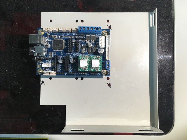
Here’s the Cohesion3D board, oriented so the USB port is on the left so it will stick out the slot in the side of the laser cutter body (just like the stock FSL board did.) I marked where the holes needed to be drilled and then…

cohesion3d-005

I drilled two holes. Luckily I was able to use the two preexisting holes on the left, so I only had to drill the other two. The standoffs used on the original board worked fine with the Cohesion3D board, and I was able to attach it easily. (Note the Mini should use plastic standoffs/hardware, while the LaserBoard can use metal mounting hardware.)

cohesion3d-006

Okay! the Cohesion3D board is now mounted in place, so the next task is to move over all the connections from the old board. Luckily I labeled them all before I removed them. I highly recommend you label them and take some photos to show how they were connected.

cohesion3d-007

The limit switches connected to the FSL board with a 4 pin connector that was “GND X Y GND” and the Cohesion3D has two separate connectors for the X and Y limit switches. I used some M/F jumper wires stuck into the existing connector and then routed to the appropriate connectors on the Cohesion3D board.

cohesion3d-008

I matched up the GND and SIG wires for the limit switches. Note that I just grabbed some random colors of whatever M/F jumpers I had on hand. With just 4 wires simply connected I’m not too concerned with color coding or labels.

cohesion3d-009

The next step was to take the 6 pin connector that plugged into the FLS board and remove the 4 wires in it. I did this by pressing against the tab of the metal connector with a small screwdriver until I could slide them out by pulling gently on them.

cohesion3d-010

Once I got the wires out I had to modify the connector, first cutting it down to be just 4 pins wide instead of 6 so it would fit in the Cohesion3D board.

cohesion3d-012

I used a utility knife to press down on the connector and cut off an end with two connectors. This worked, but I think a saw would have been a better option. (Sorry for the poor photo!) One thing to notice in the photo is a triangular wedge part on the connector. We need to remove that because we’ll rotate the connector 180 degrees for the Cohesion3D board.

cohesion3d-013

Another poor photo, but hopefully you can see the bottom part of the connector has the triangle wedge thing removed. I put it on the belt sander until it was gone.

cohesion3d-014

I had to determine which wire was which so I could line them up properly, so I removed the other end of the connector, which was on the power supply. I couldn’t quite see through the plastic to figure out the order, so I used a multimeter to check each end to figure out the wiring.
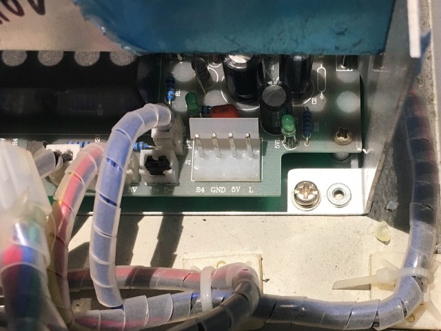
cohesion3d-015

On this machine:

  • 24V was red
  • GND was yellow
  • 5V was blue
  • Line/Laser was green

cohesion3d-016

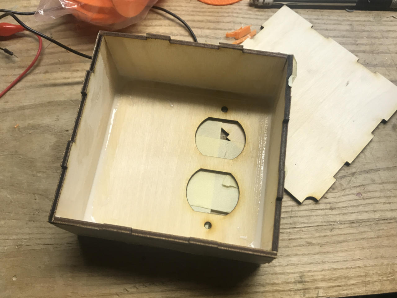
Here’s the order, but the blue wire (5V) is not needed, so I didn’t even connect it, I just taped it up. The other 3 wires I put into the connector.

cohesion3d-021

With the wires inserted (except the 5V blue) and the triangle wedge part removed, we can now plug it into the Cohesion3D board. You should definitely consult the Cohesion3D Mini Pinout Diagram while doing all this.

cohesion3d-017

Let’s not forget the stepper motors! These were the easiest, as the connectors matched up fine. The one thing I found out later is that the Y motor connector had to be flipped. So while in this photo the red wire is on the left, I later rotated the connector 180 degrees so it was on the right. This is the nice thing about stepper motors, if they go the wrong direction you can usually just flip the connector around.

At this point I put everything back together, closed it up, and was able to jog the motors to move the gantry around. As mentioned, the Y was originally reversed (like a standard Cartesian 3D printer) but I fixed that. The other issue was that the laser did not fire. I rechecked everything, messed with the config file, and still nothing…

cohesion3d-018

Yeah, see that red button that says “Laser Switch”? It was off. Once I turned it on, I fired the laser! The limit switches worked, the motors worked, the laser worked. It all (mostly) worked! I say “mostly” because while I am able to run jobs and laser, there’s still a little bit of configuration to do, so we’re only about 95% done, but… we’ll save that for next time.

I’ll also talk about the software and firmware in the next post, but for now I just wanted to get the board installation covered.

Note: First good config file can be found here: https://gist.github.com/raster/29f1e86896f7b74f0ee56ab35b87da2b and most recent can be found here: https://github.com/raster/RasterLaser