Categories
Uncategorized

Fusing 3D Printer Filament

I’ve know about fusing the ends of filament together for at least a decade, but never really tried doing it. Until recently… I tried a few different methods, I did a bunch of reading, watched some videos, and I failed at nearly all of the attempts, or just wasn’t satisfied with the results. But somehow along the way I absorbed enough information to try something, and hey… it worked!

Note: Just want the files? Get them from Printables.

I read a lot of posts, and watched a lot of videos, and I feel that it’s sort of like 3D printing itself – what works for one person may not work for another – so find what works for you and go with that.

The method that is closest to what I did can be found on the Filament Splicer & Joiner with Roll Holder page. Rather than go through all the trouble of printing those parts and assembling it all, I took a simpler approach and went minimal to test things out.

The Tube
I ended up using this PTFE Tube (which is 1.775mm~ ID / 2.5mm OD). Wait, why is this important!? Most PTFE tube used in 3D printers (to feed filament to the machine) is 2.0mm ID / 4.0mm OD. Many methods use this size tube, and the issue is that the filament expands to 2mm inside the tube. The recommendation is to then shave and/or sand down the filament to get it back down to 1.75mm. This method constrains the filament to a dimension much closer to 1.75mm.

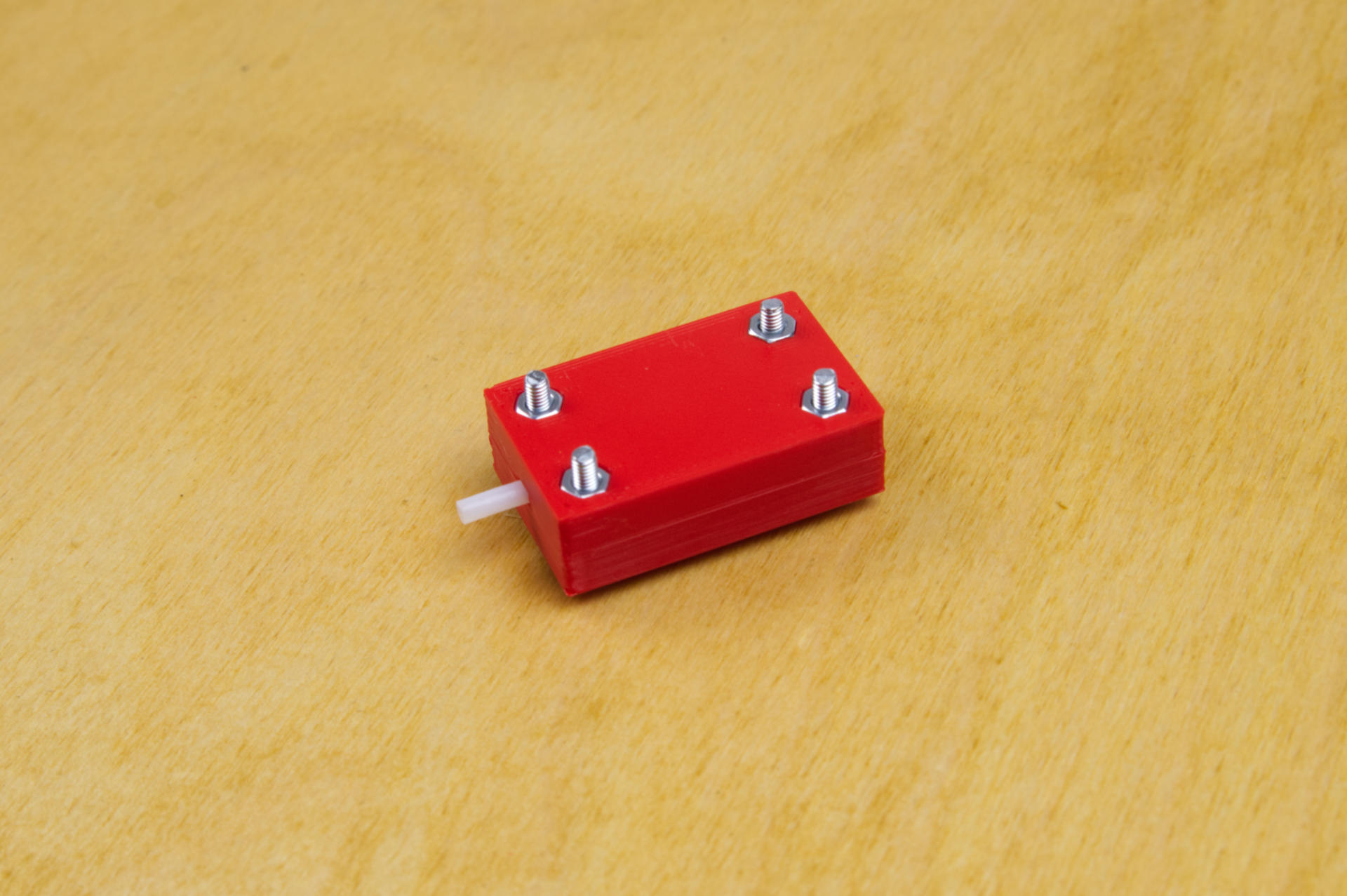
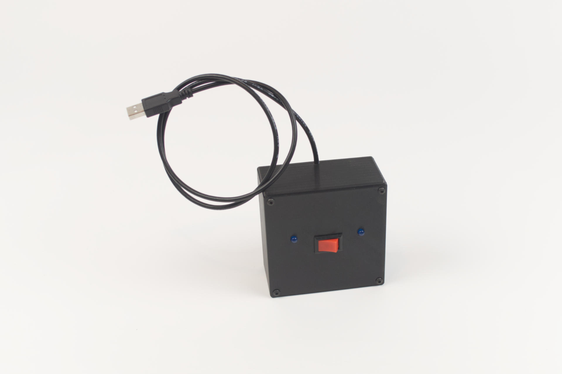
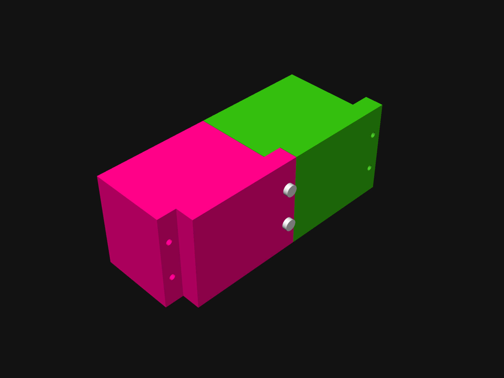
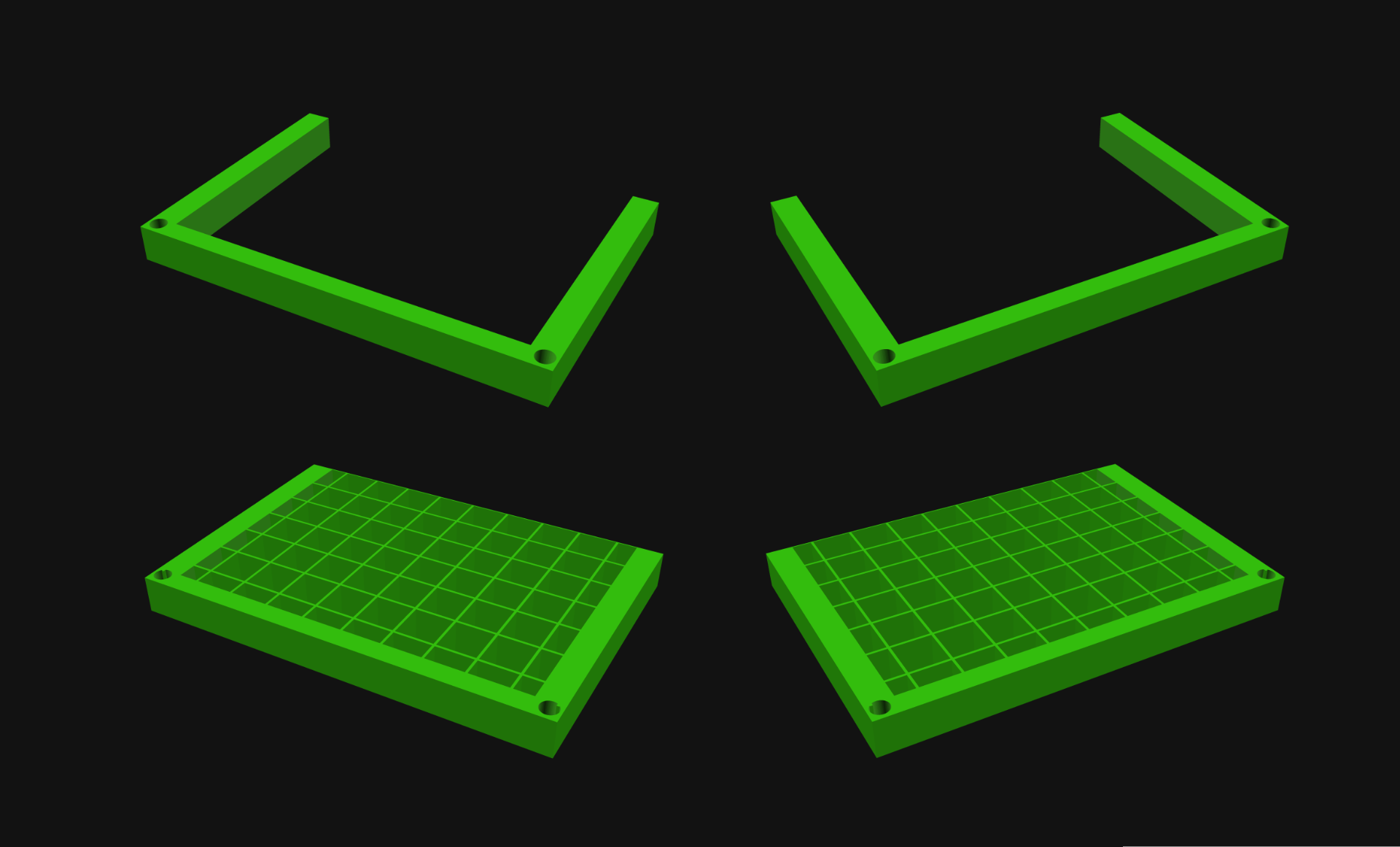
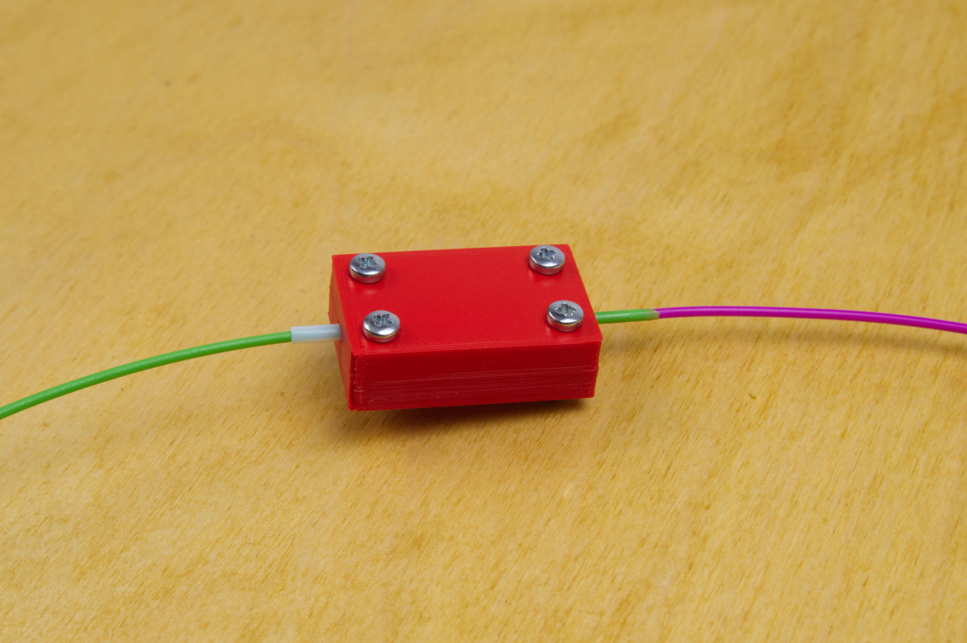
Besides the tube (which is the most crucial part of this whole thing) I designed and printed two parts and added a few 3mm bolts and nuts to hold it all together.

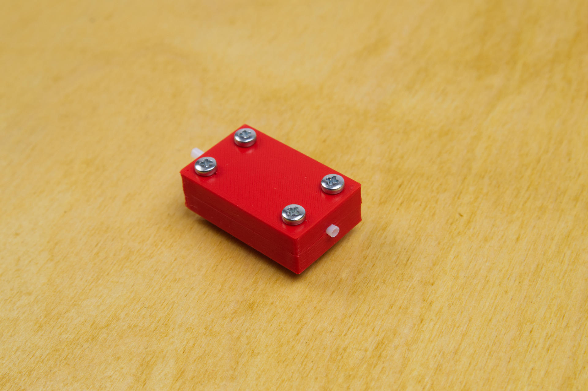
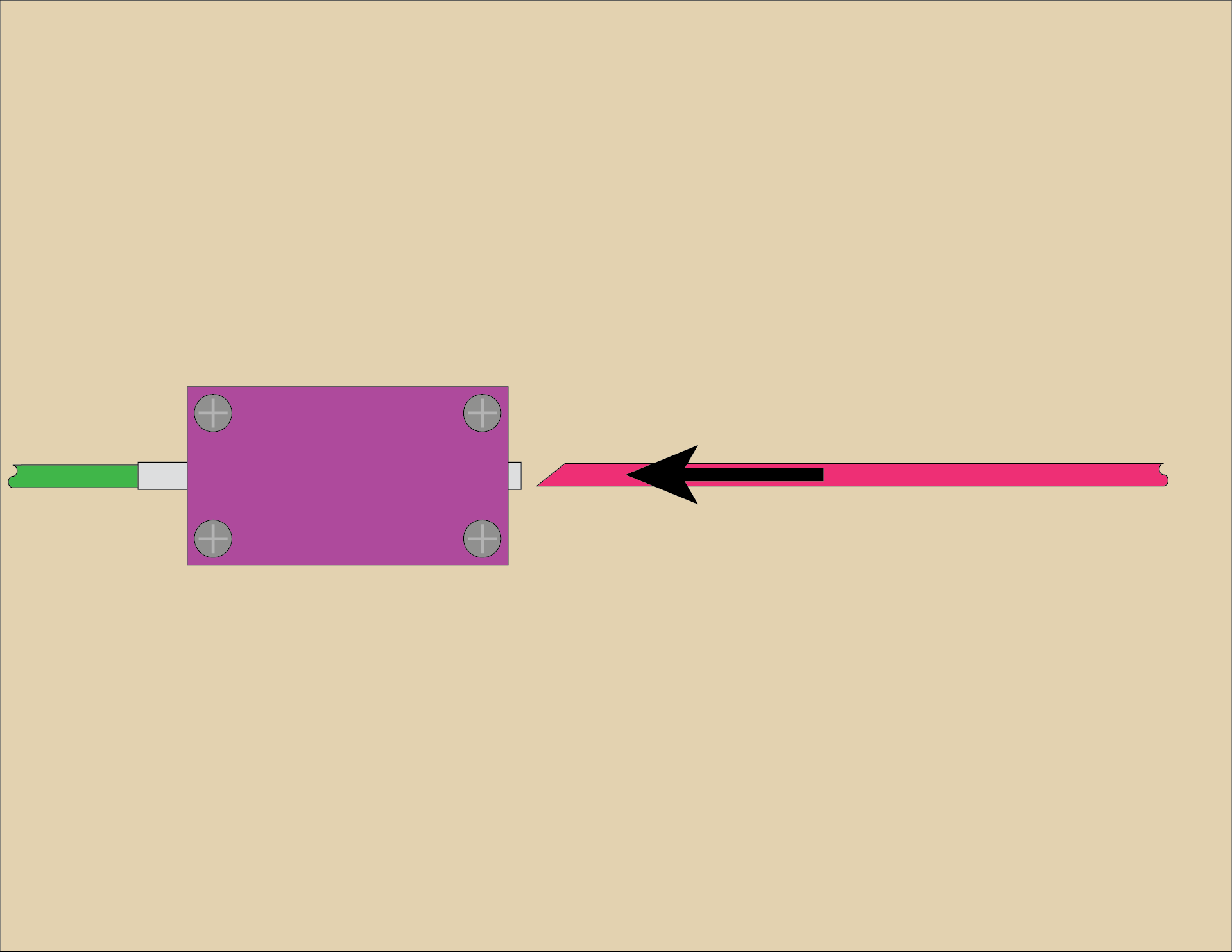
You’ll notice a long end and short end of the tube sticking out of the device. You’ll want the short end to be the business end. I probably could have trimmed the tube down on the back side but it’s okay to be a bit longer. Just keep the other end barely sticking out as shown.

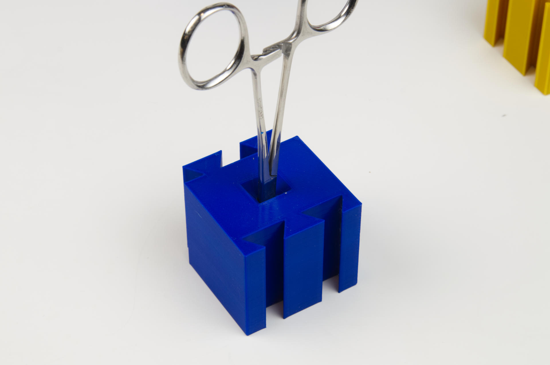
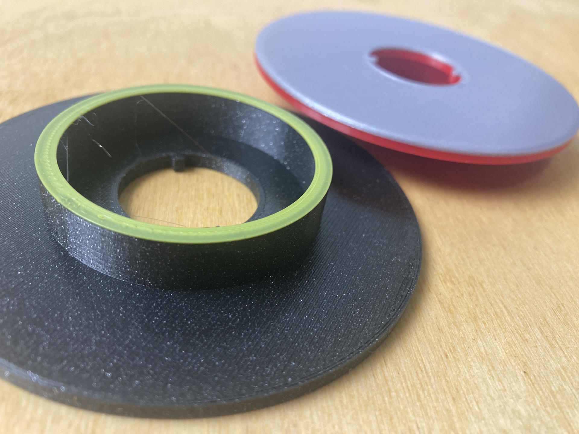
I also used a vise to hold the device securely in place (I can see why Turnt use a clamp design) and also grabbed a candle… and of course, some filament!


I’ll try to produce a quality video but in the meantime here’s an illustrated guide demostrating the technique. (And yes, I did mix up the colors as compared to the photos! You also won’t see the vise in the illustrations, so just pretend it’s there.)

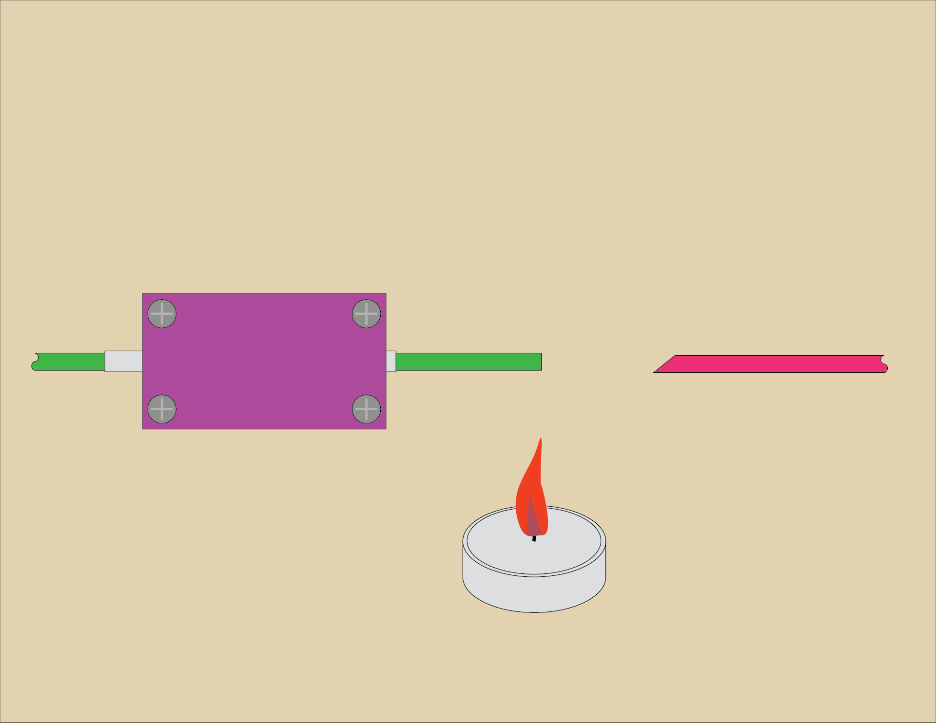
Insert a piece of filament from one side and slide it all the way through. It should have a flat cut end on it. This is the piece we will heat up. The other piece (on the right side) should be cut at a 45 degree angle. The angle is primarily to allow you to quickly and easily feed it into the tube without fiddling about.

Put the filament over the candle flame and it should start to soften. Don’t get it too close, or it will catch on fire and burn! Start with the filament further away from the flame and slowly move it closer. I think around 100mm is a good starting point.

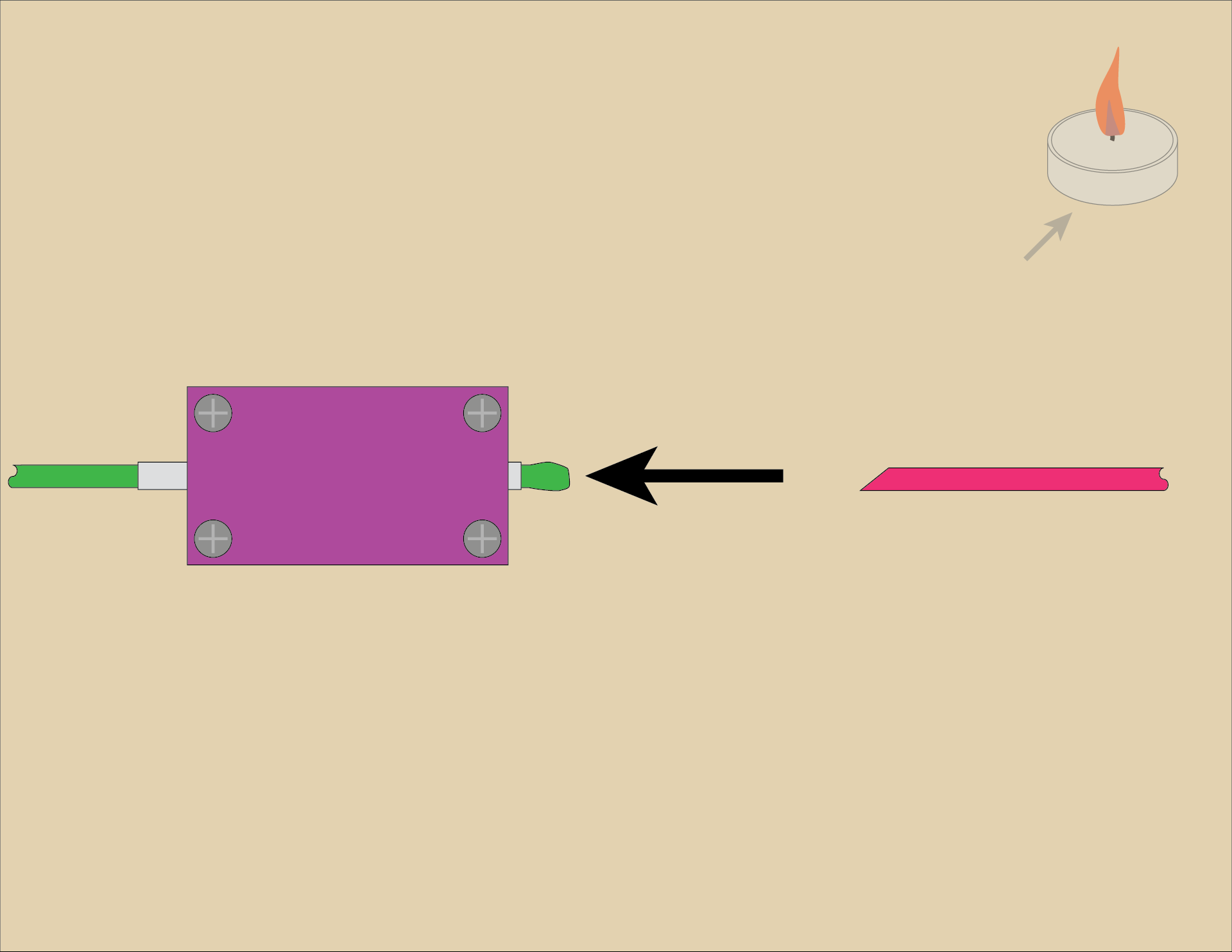
Once you see the filament end soften into a blob pull it back into the tube… You’ll need to pull it in about halfway into the device. Practicing a few times will help you get it right.

At this point you may want to move the candle out of the way, or just blow it out for safety.

Once you’ve pulled the heated filament into the tube quickly push the other piece of filament (with the angled end) into the tube.

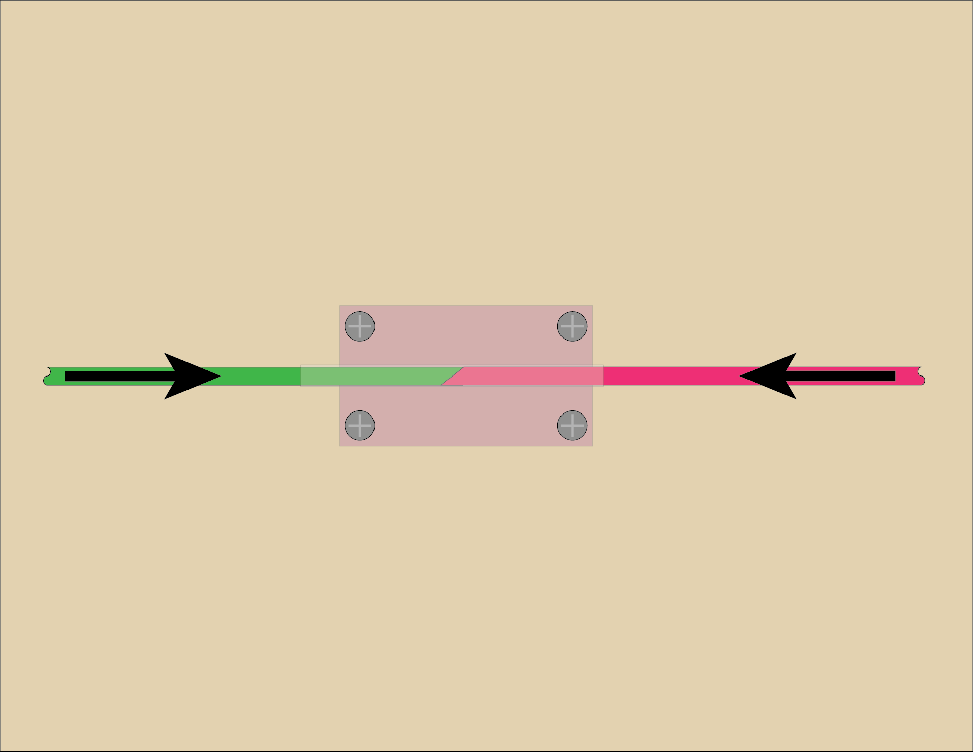
Now you should be using both hands, holding both pieces of filament, pressing them against each other. Push and hold. You don’t need to push with all your might, but give some good pressure. Wait a bit for it to fuse and then cool… 30 seconds should do it.

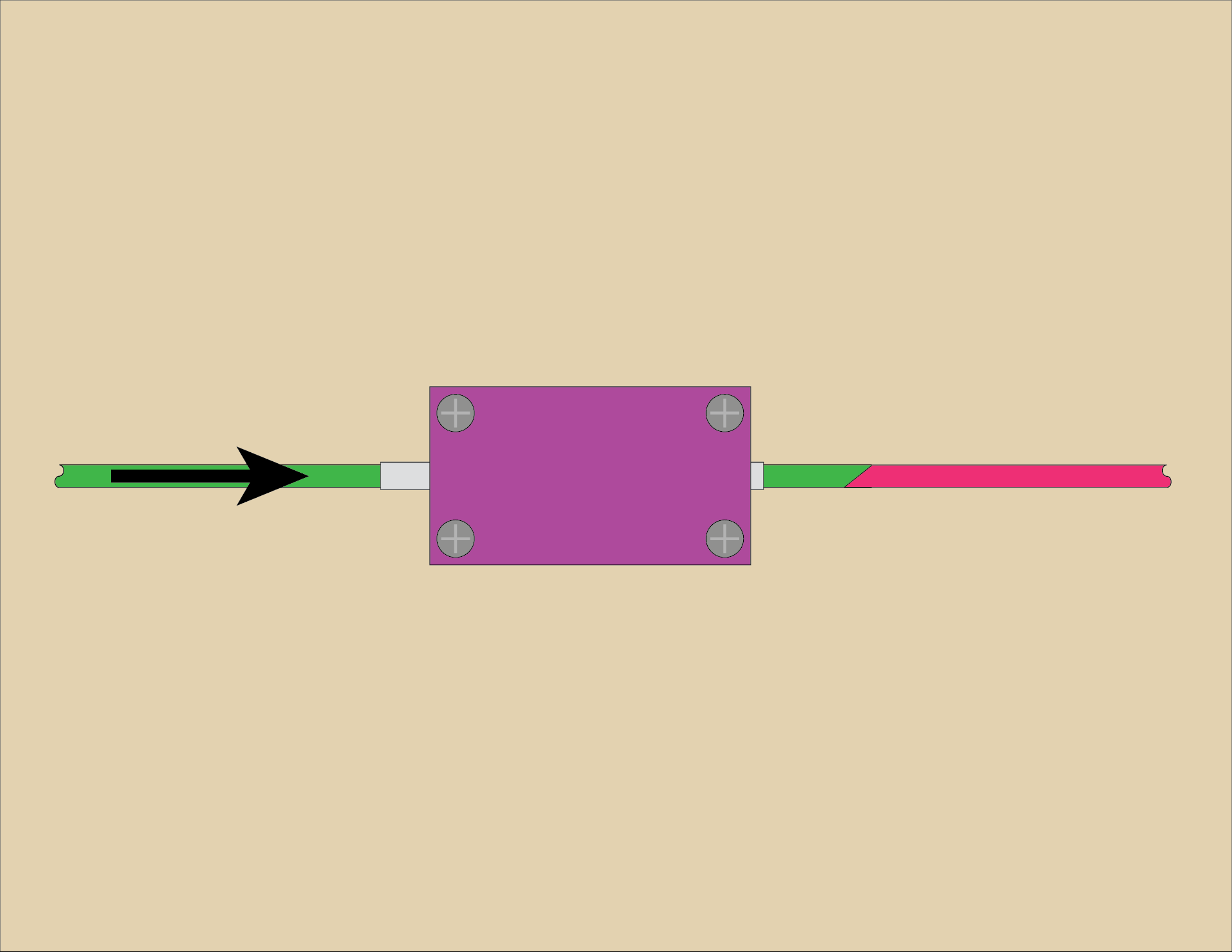
Now push/pull the filament out again, and inspect it. Give it a (light to medium) tug to make sure it doesn’t come apart. If it separates, cut the ends and try again.

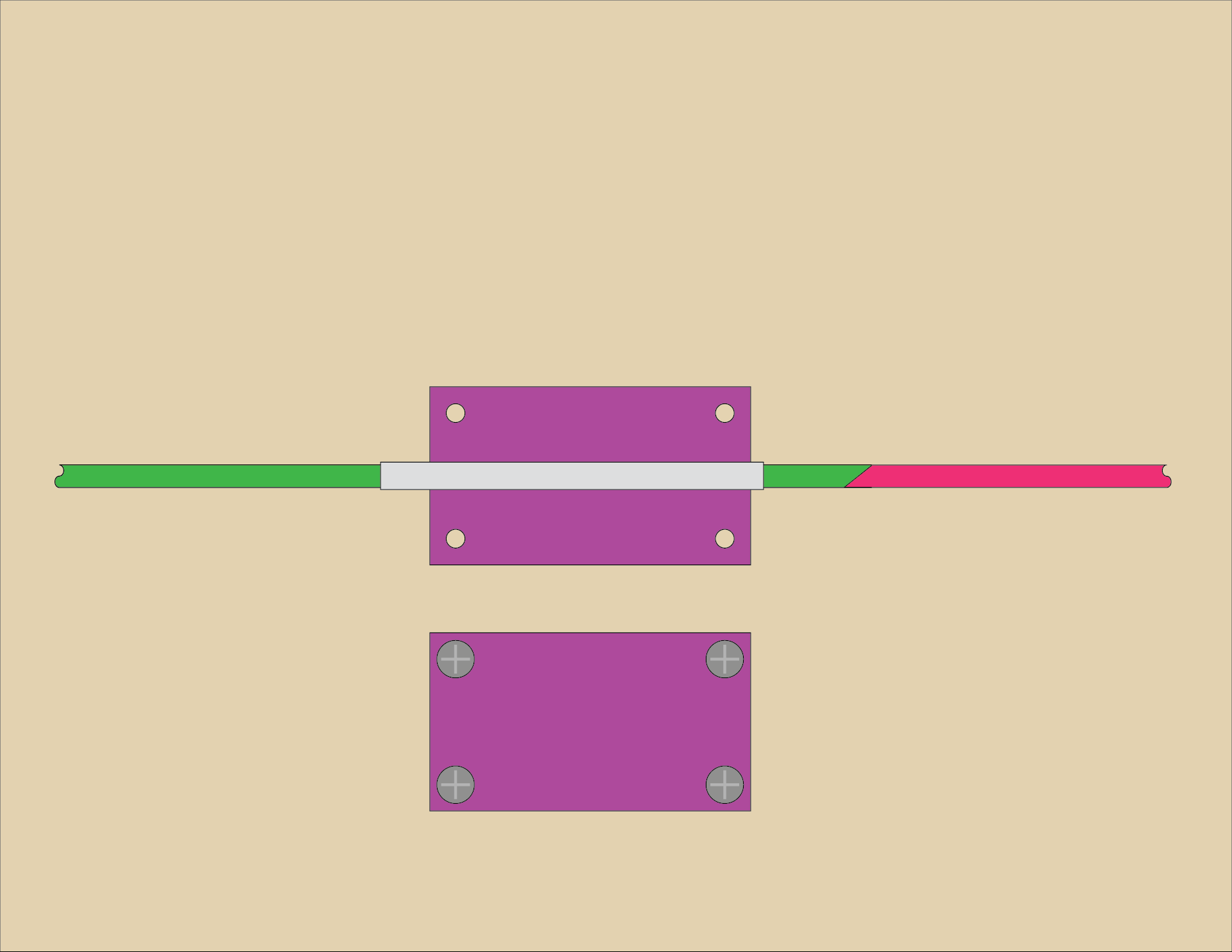
If you find that you cannot push/pull the filament out of the tube you can loosen the screws to release the clamping on the tube, or separate the top and bottom pieces completely so the tube can be removed from the assembly. This can make it easier to slide the filament out. You will obviously have to slide the tube completely off of the filament piece. When doing this I’ve probably got a spool on one end so I’ll slide the tube away from the spool to free it from the filament and then spool it all up.

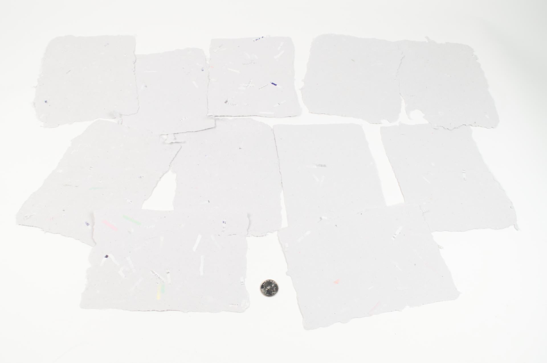
Using this method I joined about a dozen pieces of filament into a portion of a spool and then did some test prints. Are they the greatest prints ever? Probably not… Since I mixed multiple colors and brands together I’m sure the filament profile, which should be tuned for a specific filament, sort of goes out the window. Still, the results were completely acceptable and I’d rather find a way to use up all those short bits and unspooled samples I’ve collected over the years.
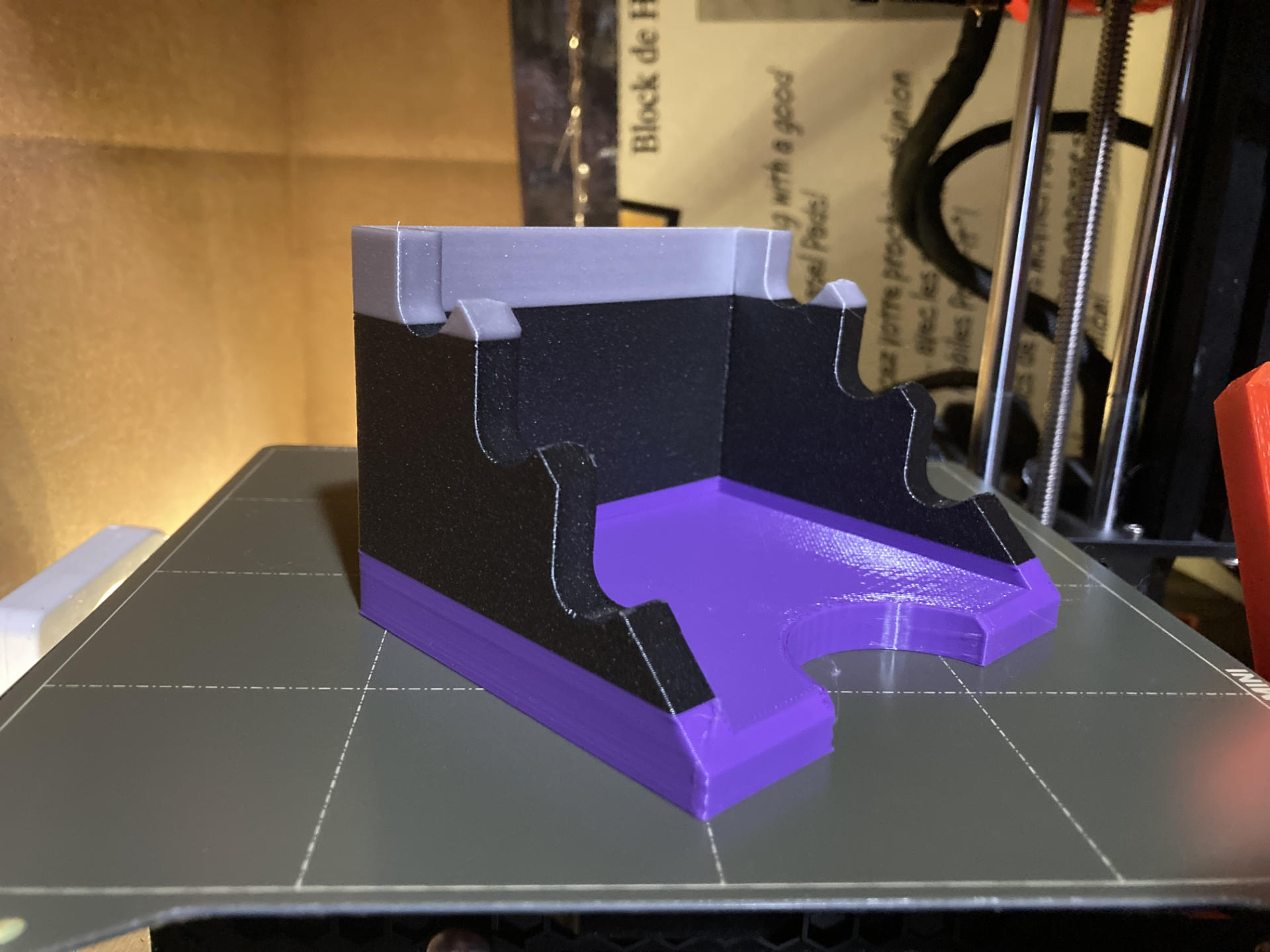
The Device
You can get the STL and .scad files from Printables.com – Simple Filament Fuser. Print it if you want to give this a try…

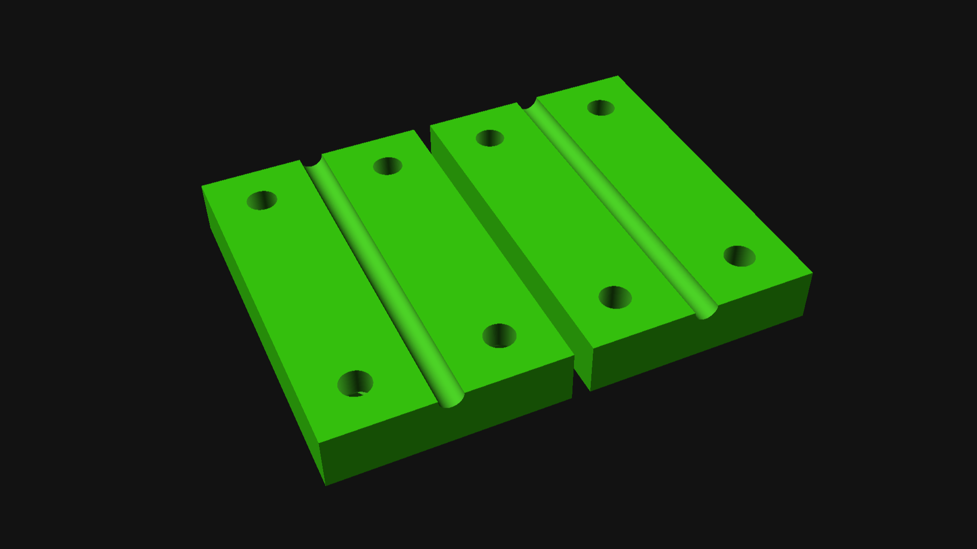
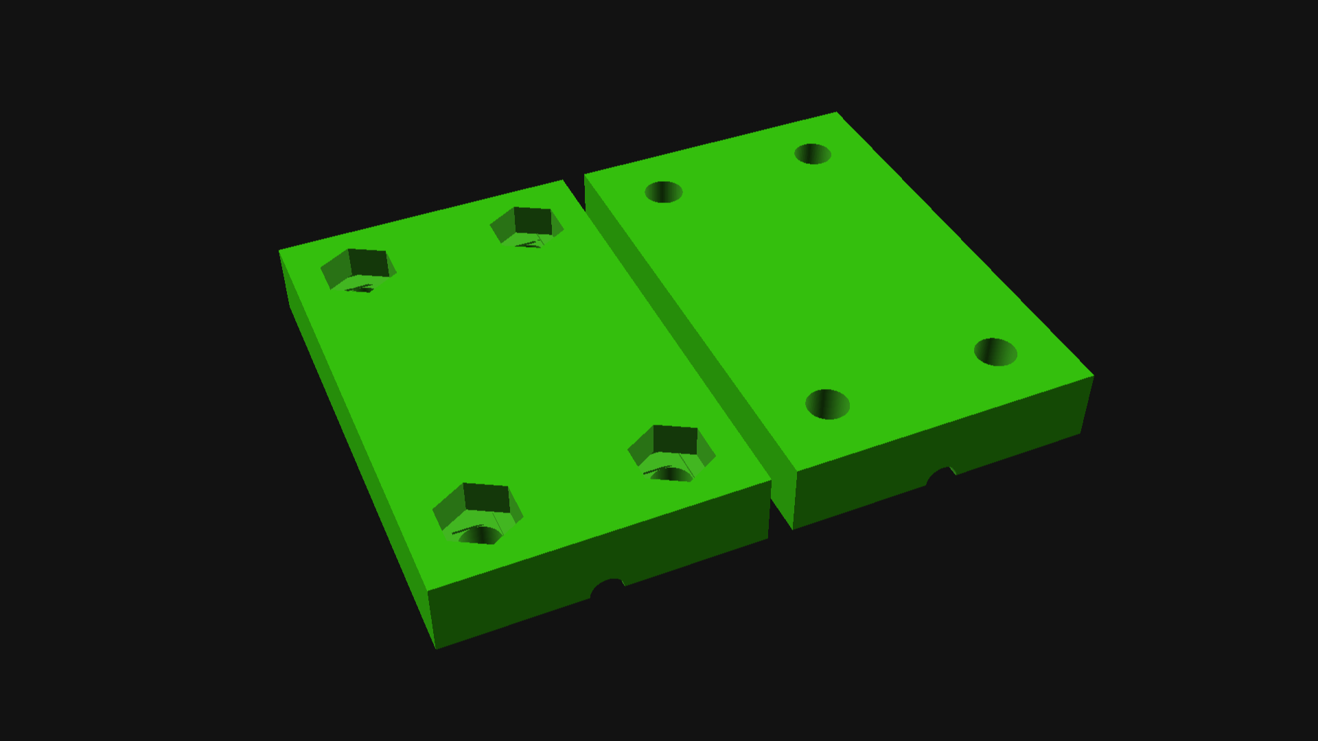
You’ll need four 3mm x 14mm (or longer) bolts and four 3mm nuts to assemble the device. You can probably use #4-40 bolts & nuts as well, or adjust the size of things in the .scad file to suit your needs.

If you end up making this and using it, please let me know. Did it work? Did it not work? What was your experience? Any tips or tricks to share?


Update: Don’t like the DIY route? This Filament Welder device is somewhat similar, but reading the reviews suggest you will need to shave/sand down your joints, and you may also benefit from a few of the tips I’ve shared in this post.

Categories
Uncategorized

Simple USB Switching Device

I recently sold a USB controller to a large company and then the Experiential Marketing Team there had a few calls with me about what they wanted to do next, which was build a “very large” controller. I gave them a huge quote (because it would have been a huge project involving custom fabrication) and they eventually got back to me saying they found someone local who would do the fabrication, but wondered if I could still do the programming part of it. I said “Of course!” and we got going…

As we talked through the project I realized that if I just sent them a microcontroller with a bunch of bare wires it may not be the best experience for them, so I offered to build a prototype/testing unit that would be fully functional, and then also provide the “bare wire” version they could install into the custom fabricated unit they were having built.

One of the people asked if they should have a backup in case of failure, and of course that’s always a good idea so I said I would throw in a spare as well.

Projects like this tend to be pretty easy for me. I’ve got my own OpenSCAD library to easily create the enclosure with the holes I need, and I can easily add new holes as needed. I can choose to print the top lid integrated or separately (and attach with hardware) and I tend to do the lid separately now because it means faster printing, less support material, and I can easily iterate when needed.

The electronics for most controllers I build is the same, so if I don’t have code that does what someone wants, it’s fairly simple for me to rewrite existing code to do what is needed. I test things on macOS and Windows for every project, and Linux if that is needed. (It is sometimes, but it’s rare most of the time.)

Anyway, a project like this is actually pretty fun for me, which is why I keep doing them. I can get away with not charging a ton because I have my system down really well to produce what people want.

Categories
Uncategorized

The New Tool Holder

If you’ve seen my post The (Old) Tool Holder and The (In Progress) Tool Holder then this one is just another in that series and I’m going to ramble on about a few things in the process…

Here’s the final result of what I’ve been working on (on and off) for Wow! Almost a year… I mean, the on and off part meant I took huge breaks for months without doing anything…

The original plan was to replace the old tool holder at my soldering station with a 3D printed “modular” system. See, instead of printing one (or two?) giant blocks with specific holes in specific places, the blocks would allow for easy rearrangement… and the dovetail was a nice way to connect them (but not permanently).

Each tool had a block designed just for it. Well, the blocks are all the same, except for the hole/slot the tool went into. Each tool went it with the handle sticking straight up making it easy to grab.

I eventually removed the block that held the round file because I really wasn’t using it anymore in my soldering. (I had one weird specific thing I used to use it for.) That was the nice thing about separate blocks! I could easily remove one, add in a new one, etc.

To be honest though, I am just not sure the dovetail was the best idea… When I started it was a really fun challenge to get the tolerances just right, which was really easy on my Prusa MINI+, and not at all easy on my old Monoprice Maker Select Plus. (I guess + is better than Plus!)

So while the dovetail is neat and interesting… it may not be the best solution for this specific thing. It’s still a great way to connect certain things, and I love when digital fabrication can borrow from traditional woodworking techniques… But I also realized (again) a few months ago that sometimes it’s just dead simple to use a screw to attach two 3D printed parts.

When I mentioned this recently someone assumed I mean “drill a hole and stick a wood screw in there” but what I meant was “put holes into the two things you are printing and put a screw in there”.

So I did a quick design for a “lap joint” style version of the blocks. Each would connect with 3mm screws, probably 12mm long or something. I have a huge collection of 3mm hardware that I use for so many projects that using it should be a no-brainer when doing this stuff.

I also found that I didn’t rearrange the tools much once I got a configuration that worked. If I used screws to hold things together the power screwdriver would make it pretty simple to pull them apart and rearrange them anyway.

I don’t know that I’ll redo the Tool Holder (yet) because it does work just fine, and if I’m honest I’ve got other things that need organizing. In fact since I just started building a Gridfinity system I wondered if I should make a Gridfinity version of this thing… but I don’t think I will right now. (Maybe some day?)

By the way, the blocks are printed with a lot of infill, because I wanted them to have a bit of weight to them, hence the size of them. Anyway, the Tool Holder is done (and has been for months now, I just never got time to finish this post!)

Categories
Uncategorized

Worx 4V Power Screwdriver

Hello friends, I am here today to tell you about the Worx 4V 3-Speed Electric Power Screwdriver (Specs) but first I will tell you about my other power screwdrivers.

Many years ago I got this General Tools Precision Cordless Electric Screwdriver for light-duty tasks like dealing with screws in laptops, or anything 3mm or smaller in the electronics projects I build. It’s not meant to crank a screw in super-fast or super-tight, but meant to help prevent having to crank your wrist in a twisty motion dozens of times. (Note: As you get older, you get more tired faster, and things tend to hurt more.)

The size is just right for delicate work, and my only complaint is that it is maybe a little under-powered. It uses AAA batteries, so no built-in rechargeable battery in this one, which has its own pros and cons. It uses the small 4mm tips so I use it for small things.

Around the same time I got the small one I also wanted a larger power screwdriver I could dedicate to a specific task in the production of the products I make. This Black + Decker 4V (pistol-style) screwdriver. It works well for putting screws into enclosures as well as more medium to heavy(ish) duty things. I don’t drill big screws into wood with it because I have tools for that, but in a pinch it’ll drill small holes into wood for #4 screws pretty easily. (And I’ve done that a number of times building exhibits.)

The pistol-grip style makes it ideal for some things, and not great for other things. It’s got a big switch to change direction, so it’s a two-handed operation sort of thing. I swear I only charge the thing about once a year, which is nice.

Okay, onto the Worx! It has… features. I got this because I needed a second (large) power screwdriver in my shop, as the Black + Decker lives in one spot and has a dedicated task assigned to it. I wanted to try this style (classic “screwdriver” rather than the pistol-grip). So far I’m finding it to be a nice very well made power screwdriver, though I do have a few observations…

First, why is the switch where it is? When you hold this in your hand the natural positions for the switch would be where the logo is. To properly press the switch with your thumb you need to sort of hold the back end of it, which seems weird as I’d prefer to get a good grip on it, not just hold the last 1/3rd of the device. (To be fair, the first powered screwdriver I owned about 30 years ago, was probably close to twice the length of this one, so a shorter tool is appreciated in this respect.)

The torque switch is at the very end. Again, it might make sense to have that closer to the front. Maybe the battery and motor placement dictated the position of the switches… I don’t know, but it’s not really optimal for how I use a power screwdriver.

It comes in this box, and I do appreciate a nice enclosure. The fact that the top lid is transparent is awesome. You can see if it’s in there! If you’ve ever opened a tool box to grab a tool and it’s not there… well, this solves that problem.

Okay, this one is subtle. Did you know that 90% of the population is right handed? This case appears to have been designed for left handed people. My natural inclination (as a right-handed person) is to grab the tool with my right hand and remove it, but it’s facing the wrong way. How can I tell it’s facing the wrong way? Look at the logo… it’s upside down.

I do like the fact that you can leave a bit in it while it’s in the case, and the small retaining ring that prevents the tool from falling out is also a nice touch. And, there are bits, which is great. There is also some extra empty space. The charging cable was originally in the cavity, but you could throw more bits in there, or screws, or… design and 3D print something that fits in there perfectly, and maybe holds even more bits! (Yeah, I might do that.)

If you remove the insert, the printed manual is below. Another nice touch. And as mentioned, you can fit the charging cable down there. You could probably fit more bits or other things down there as well.

Just for comparison the General screwdriver was about $20, and the Black + Decker was also about $20. The Worx is around $30, which isn’t too bad. But what if you want to spend a lot more? Well, there’s the Mini ES121.

Here’s a Mini ES121 on Amazon for $268 which seems insane. Oh wait, an ES15 is less than half that price. Still too much? There’s a Wowstick for under $50. You can probably find them (or knockoffs) cheaper on AliExpress or other Chinese web sites…

To be honest I don’t know that I need any more screwdrivers right now. NotEnoughTech has a good review of the ES121 and the Wowstick if you want info on those.

Happy Screwing!

Categories
Uncategorized

Paper Making (Again)

I made some paper… again. The first attempt used a small 3D printed mould and deckle, and this time around I made a new (slightly larger) mould and deckle.

I also experimented a bit more with the paper, this time using paper from our paper shredder and mixing in a few “raw” pieces to some sheets. The results are definitely interesting.

I tried a new technique with the hydraulic press after they were all dry as well. Last time I stacked them all and flattened them in the press, and you can see the screen texture in those. This time I did that, and then followed up with pressing them with a piece of wood between each individual sheet. Some of them came out incredibly flat and smooth! I’m curious to see how they take ink when printing on them.

Some of them are a lot more ragged around the edges. (That’s the “deckle edge” you know.)

Here’s a few I added shredded paper to that was not blended or soaked, just tossed onto the pulp before drying. It seems embedded really well and certainly gives a look.

A bit more closeup view… you can see and read some of the type, which I think could be really interesting since I used shredded (and potentially sensitive) documents. There’s probably a whole project there all on its own.

Because I printed this larger mould and deckle on my (small) Prusa MINI+ I split it in half in OpenSCAD, printed the parts, then glued them together. When assembled this one is about 165mm x 224mm and the paper comes out around 145mm x 204mm.

Printing in halves and gluing together mostly worked. I had to print small shims on the side to make it more rigid, but now I really want to make an even larger one! (Though I will need a larger pulp bucket then.)

Magnets embedded into the corners of the mould and deckle work to hold the whole thing together with the screen between the two parts. I’m happy with how this turned out. I just made holes and stuck 1/4″ cylindrical magnets into the holes (making note of polarity) and then shot some hot glue in the holes to hold them in place. (Yeah, sometimes hot glue is quicker and easier than perfectly modeling a hole with friction bumps.)

Despite a few issues combining the halves to make a whole, I’m quite pleased with how the mould and deckle turned out, and I’m sure I’ll experiment with others in the future, especially since it’s trivial to make any shape… round, hexagonal, triangular? No need to be confined to a rectangle. (And yes, I’m very happy with the paper as well!)