Categories
Uncategorized

Casting Wax using Silicone Molds

wax-mold-00

I’ve been experimenting with casting for the last year or so and typically my “experiments” come out terrible, mainly because I try weird things, but sometimes I sort of get it right…

This time I made a silicone mold of a model of a glue stick for a hot glue gun and it mostly worked fine. I modeled a glue stick and tall cylindrical container for it using OpenSCAD and then 3D printed the two pieces. The idea being I’d place the “stick” into the container and then pour silicone in to create the mold.

wax-mold-01

I had a small amount of silicone we were going to throw out at work because it wasn’t enough to do anything useful with, and it was just enough after scraping everything out of the two containers and mixing it together.

wax-mold-02

Once again I had to destroy the original mold master to get the mold out, but since it was printed using PLA I just smacked it with a hammer a few times and peeled away the plastic to get the silicone mold out in good condition.

wax-mold-03

I could not find the cheap little cooking pot I bought at Goodwill a few years ago for melting things so I grabbed an old metal can, made a makeshift gaff tape handle, and melted down some old candle wax to pour into the mold.

wax-mold-04

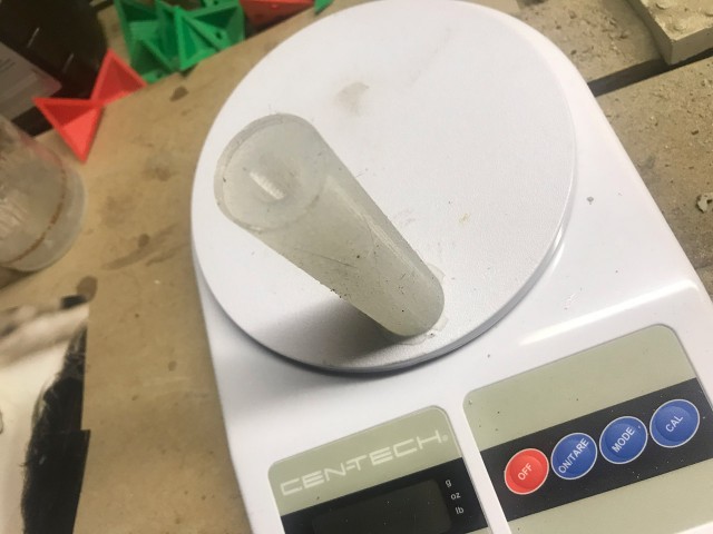
Hey, it worked! A wax stick the same size as a glue stick you would use in a hot glue gun. ;)

Oh, see those rubber bands? They hold the mold together because I split it down the side to allow for getting the wax out of the mold. I may have wrapped the mold too tight or not aligned properly because the first stick wasn’t totally straight.

wax-mold-05

Here’s the second one… much better. You can see the split in the mold. I just ran an X-ACTO blade down the sides to split it.

wax-mold-07

Now, to ramp up production I may need to make a lot more molds, or come up with an alternative. Here’s a method using a metal tube and parchment paper that might work. Honestly I think I prefer silicone molds but this might be a good way to get really long sticks.

wax-mold-06

The next part of this experiment requires a hot glue gun, and most likely, disassembling it for the heating element. Stay Tuned!

Categories
Uncategorized

RepRap 6000 Review…

reprap-v20-diagonal

In my last RepRap post I had modified the design to be much wider in the x and y planes, and as I did that I started to realized that it would cause a number of issues with the build. I mainly did this because I have plenty of Aluminum extrusion to work with, but as I thought about it more I started to remember why 3D printers are mostly the size that they are.

When you go beyond the typical build envelope of most 3D printers things get complicated. You can’t use 8mm rods because they’ll sag under the weight they carry, and if you make them long enough they’ll even sag under their own weight, so you need to start using other methods of linear motion. I thought about following some of Mark’s lessons from SoM, but things get expensive when you start doing that. (He does manage to scrounge and buy used things, but that can be tricky as well.)

I will definitely follow some of Mark’s techniques though. For instance, look at this build for the BA3DP. Start counting the amount of hardware used for those corner plates. Crazy! The Mark Method is to tap the (milled square) extrusion and screw it together. Simple! And you can always add some corner brackets if you want, but they aren’t as necessary and definitely don’t need as many nuts and bolts.

Some printer designs use T-slot frame members joined together with printed plastic parts. Avoid the temptation to do that. If you want rigidity, you have to bolt/weld metal to metal. T-slot extrusions are designed to accommodate standard sized screws. All you have to do to join two pieces is drill one hole and tap the end hole to receive the screw. Likewise, attaching things to the T-slot can be done by using nuts designed to fit the slots (or by making your own).

That’s my plan for assembling a rigid square frame using 40mm Aluminum extrusion. Speaking of the extrusion, here’s a test fit for some of the printed parts. I’ll probably start with these and tweak if needed. Mark suggested I make the motor mounts from square Aluminum tube, and that might be a future upgrade, but I’m okay to start with some printed parts. I do want to try to reuse many parts from my old RepRap, and use parts I have on hand, so I’m going to try to stick to that plan.

extrusion-01

One thing I don’t have is 12mm linear bearings for my y axis. I’m going to try igus drylin linear bearings. I’ll need to make mounts for them that compress them a bit so they fit properly. I’ve read enough to know you can’t just zip tie them into place, (To be honest, wires are the only things I plan to zip tie into place.)

I still need to shop for hardware. Either 5/16″ or 8mm bolts, depending on what I’m ordering from BoltDepot or buying locally in the coming weeks.

extrusion-02

One thing I’m still not totally sure of is where the vertical pieces of the gantry will sit yet. I’ve tried to calculate where to place it so that the extruder will reach the front and back of the bed properly, but I still don’t have that nailed down… partly because I’m still not sure how the x axis and carriage will work as far as mounting the hot end, connecting to the smooth rods and lead screws… I also want the carriage to be easily removable, and possibly replaceable with, another end effector. :)

reprap-v20-top

Since I’m going to avoid going wider than I need to for this printer, I can get away with 8mm rods for the x axis like I did with my old RepRap. I’ll probably sacrifice a little rigidity and precision, but that’s a price I’m willing to pay right now to avoid paying more for a proper linear guide on a square Aluminum tube. (Future upgrade?)

I’d like to keep the x axis motor within the envelope of the machine, and not hang it outside as many printers do, but I’ll need to design that as I’ve not found a solution yet that fits what I want. Time for more CAD work I guess.

Categories
Uncategorized

RepRap Z Motor Mounts

bracket

As the RepRap build continues, I designed some motor mounts that will work with the 40mm extrusion I’m using. The Nema 17 stepper motors I’m using are about 43mm wide, so they hang just outside the extrusion if centered, so I’ve designed the mount to be slightly off-center so the motor do not hang outside the frame.

mount-rails

I’ve incorporated the model into the overall render of the printer. I don’t have the hole yet for the smooth rod to fit into the mount. I’m looking at models like this one to base my work on.

reprap-6000

I’ve also worked on the full model a bit, and made it slightly larger for reasons I’ll get into in a future post. I’m currently thinking of a few ways to make this machine a bit more flexible in its capabilities, and a larger frame made sense for that. (And it means I can waste less extrusion when I cut it down to size.)

motor

Things look wonky in this photo because that’s actually a piece of 38mm (?) extrusion I had handy, since all the 40mm is at Milwaukee Makerspace right now. I’ve got a few projects to wrap up before we cut down and mill the extrusion, so I’ll probably keep working on the printed parts for a bit.

Categories
Uncategorized

Velocity Exhibit

Velocity_Loop_5507

You may have already seen John’s post about our Velocity exhibit, and I must say, he did an amazing job with all of the CAD and CNC work to build it.

Velocity_CK_5503

For my part, I handled the technology that went into the exhibit. (Which sadly, you can’t see much of in these photos because some were shot after things were powered down.) For three of the five components, I spec’d the hardware and worked with a software developer to upgrade the old version of the software to something more modern, stable, and easier to calibrate and support.

Velocity_CK_5525

I can’t even tell you how many golf balls I rolled down all of those ramps. At one point we had an issue with a projector overheating and I set up a time lapse camera to run all day and overnight to give us some idea how long it was staying on before shutting off. We eventually fixed it by adding a duct to the projector housing to draw the heat out and away. We’ve used earlier models of this projector with no issue, but this is why we do extensive testing… you never know what problems are going to pop up.

Velocity_Dish_5527

If this exhibit looks familiar (!?) it might be because there are now three copies/versions of it. Besides this one which was a “for sale” item, we’ve got two on the road, one of which will be returning to the Betty Brinn Museum this summer.

Velocity_CK_5518

By the way, if you occasionally have a bunch of old golf balls you want to get rid of, let me know… There’s a non-profit in Milwaukee who would love to take them off your hands. ;)

Velocity_Roller_Coaster_Lazy_River_5517

Velocity_Jump_5499

Categories
Uncategorized

RepRap Frame and Rods

40x40-extrusion

I managed to get the 40mm extrusion I need for the RepRap frame at Milwaukee Makerspace. Mark is our 3D Printing Area Champion and he’s managed to collect a bunch of pieces from a scrap dealer, pretty much at scrap prices!

reprap-v12

I tweaked my render a bit expanding the frame slightly, and adding in the rods and rod supports. Speaking of the rod supports…

sk12-render

I could not find an acceptable file for the SK12 rod supports. I found one on GrabCAD (which I’ve never used before) but even there I found the file formats very disappointing. I managed to convert something to an STL and I didn’t like it so I used it get dimensions and then remodeled it.

Yes, I could just buy some SK12 rod supports (eBay has some for cheap) but the last time I used cheap rod supports they were not great, so I figured I’d print them for now, and I can always replace them later. (And yes, the nice thing about having access to a good/working printer when you are building a printer is that you can print the parts you need.)

sk12

I printed one on the Prusa i3 at work with low infill to test the fit, and it was perfect on the second attempt. (My 3mm screw and nut hole were just a bit off on the first try.) Oh, the mounting holes are sized for 5/16″ carriage bolts, which fit right into the slot of the 40mm extrusion. That’s another trick I picked up from Mark. (5/16″ is just about 8mm as well.)

sk12-rods

After the second test I was satisfied, and printed the rest on my Monoprice Maker Select Plus at home. It’s also nice to have a variety of 3mm hardware I can use this time around. The first RepRap I built was a kit and came with everything I needed. (Well, in theory.) This time I’m figuring out a lot as I go, but I already have a lot of the things I need.

These linear rods are 12mm diameter and plenty long, so they’ll need to be cut down a bit. I pulled them from a large laminator I pulled apart a few years ago. As I’ve previously mentioned, I’m going to be using lots of parts I’ve been collecting over the years, so hopefully I can keep new purchases to a minimum, at least to get up and running with this printer.

(Note: SK12 Rod Support is available on YouMagine and Thingiverse.)