I was contacted by a trade show company about helping with a project on a tight deadline. At first it seemed as though they had a solution but just needed some hardware or some advice, but I did a call with the software developers and it seemed like the quickest (and most solid) plan was to create a drop-in replacement for what they were working on (and were stuck on) that would do exactly what was required.
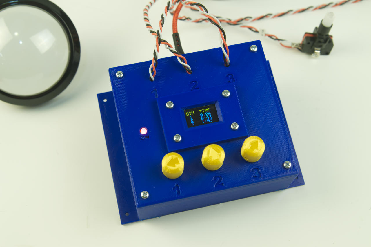
One of the requirements was for each button to be lit a specific amount of time to match the length of video playback for each button. Since we didn’t yet know the lengths of the video, and I had to ship this across the country, I suggested an easy method of setting the time for each button to be lit. This would allow them to dial in (literally) the timing once they had the videos completed.

We did know that the videos would be under 75 seconds. Just to be safe I set the timers to go up to 90 seconds (1 minute, 30 seconds, to be precise.) The controller plugs into a computer via USB and sends commands that the custom software needs to play the appropriate video.

There are a lot of details I didn’t know, but it seemed like I had enough to do my part. They sent me a rendering of a cabinet the controller would live in (which I’ve replicated in the simple sketch above). When I was building museum exhibits much of my work lived inside of cabinets and was never seen by the public, only technicians… that doesn’t mean things shouldn’t look nice.

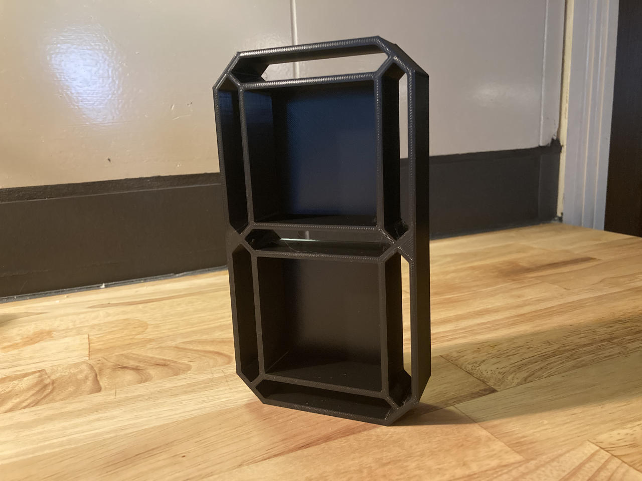
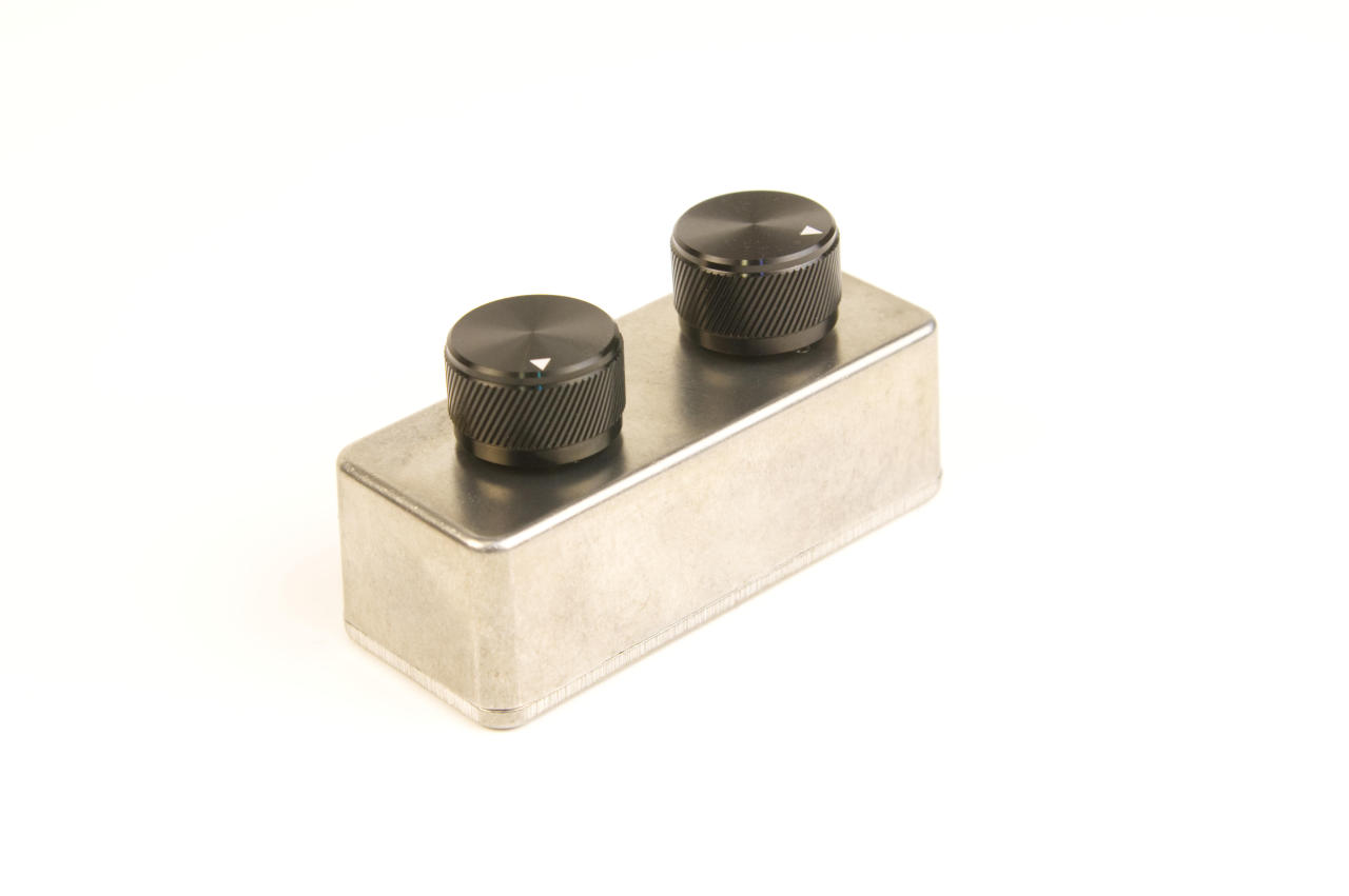
There’s a small OLED display in the controller which shows the time that corresponds to each button, and can be adjusted by the appropriate dial. The dials are 3D printed because I forgot to pocket out the back of the lid where the potentiometers are placed. There’s a few compromises that were made due to this being a rush job. (I completed this build in under a week, using only parts I had in my shop at the time.)
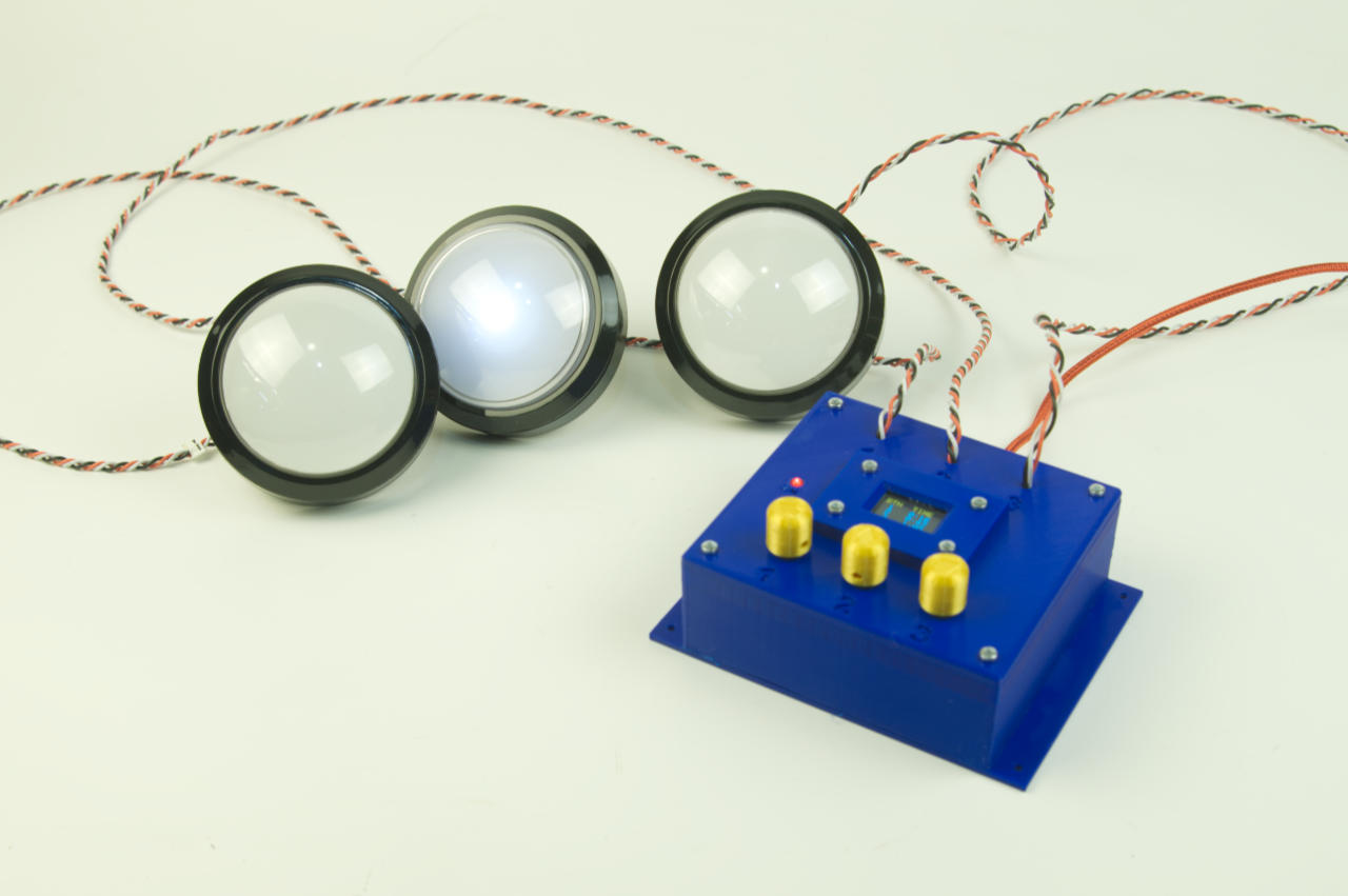
For other controllers I’ve used TRS jack and cables to connect the buttons, or on occasion, Cat5 cables and connectors. Both are nice because they are easy to obtain in any length, and trade show companies usually have a bunch in their inventory.

The bottom of the enclosure has four mounting holes, and I included screws to allow it to be attached inside the cabinet. Alternately, VHB or hook & loop could be used to attach it.
As always, if you need a device you can check out raster.etsy.com for some of the more popular stock items I make, but if you need something custom just get in touch.