Categories
Uncategorized

Red Flag

We’ve been using the RED ONE a lot in the past few months over at z2 and while we’ve had the matte box for a year now, we never managed to get top or bottom flags for it, so I finally got around to solving that problem.
RED Flag

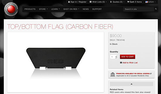
Camera accessories are notoriously expensive. For some things, that makes sense, and for others, I’m not sure it does. The top/bottom flag for a RED Matte Box is $90 USD. Well, hey, it’s carbon fiber. Yeah, that stuff is pricey! But, don’t worry…

RED Flag

There’s an aluminum version of the top/bottom flag for just $40USD. Hey, you could get two of the aluminum flags for less than the price of one carbon fiber flag!

RED Flag

While I was perusing the RED store, admiring their well done photography, I noticed that the large version of the photo was clean. Really clean, and at the perfect angle, straight on! So… I engaged in what I now like to call “R3Dverse Engineering”. (That’s “reverse engineering” of RED stuff, if that was too subtle.)

RED Flag

I grabbed the image from the web site, opened it in Photoshop, and started to clean it up.

RED Flag

I got rid of the shadow, added a white layer below so I could see things a bit better, and selected the object…

RED Flag

I then filled the whole thing with black so I had a high contrast image…

Once this was done, I saved the file as a PNG and imported it into Inkscape, where I used the ‘Trace Bitmap’ feature to create vector lines defining the image.

Inkscape Flag

The next step involved a lot of precise measurements with the digital calipers on the part of the matte box where the flag mounts. There were many guide lines added.

Inkscape Flag

The lines helped me determine centering of the slots and how wide the slots/tabs needed to be.

Inkscape Flag

I did a few revisions, and here’s the final cleaned up version. with most of the guide lines removed.

Inkscape Flag

Here’s a visual diff to show the tweaks between the original trace of the image I imported, and how much I ended up adjusting the lines a bit for a better fit. (The reddish hue shows the final. I mainly had to add a bit more space around the larger tab.)

I should mention that with each revision, I was printing out a sample on tabloid size paper and cutting it up to test the fit.

Inkscape Flag

Once my paper prototype was good enough to consider “final”, I ended up sitting on this project for a bit trying to determine what material to use, and how to cut it.

I’m still thinking about it… I’d prefer to go CNC versus trying to cut it by hand. Perhaps using the CNC Router at Milwaukee Makerspace would work. A very thin sheet of aluminum perhaps? I thought about laser cutting something, but didn’t think acrylic or wood would be a good option. I’ll need to keep thinking about materials…

Black Flag

Meanwhile, we have lots of black board at work, so I stuck my paper prototype onto a piece and hand cut it with an X-ACTO blade. (I did not round the corners.)

Black Flag

The tabs and slots are a little messier than I’d like, but again, I’ll call this part of the prototyping stage.

Black Flag

But it also totally works… and is probably less than 1/100 the cost of the carbon fiber version. It may not hold up as long, but then again, I can easily make a bunch of these for next to nothing. (I can also just laser cut the black board instead of sliding an X-ACTO around to do it.)

Black Flag

Update! I ended up laser cutting the black boards, and they works great!   You can grab the files from Thingiverse.

Categories
Uncategorized

TLBot 4: CameraPi

CameraPi

If you wondered why I needed a Raspberry Pi case that could also hold a Raspberry Pi Camera… well, seriously, don’t you people know me by now!? :)

This ‘CameraPi’ is a prototype for Time Lapse Bot 4, and if you’re not familiar with my time lapse hardware experiments, check out the Time Lapse Bot project page for a good introduction.

My Time Lapse Bots have always relied on old computers, and while you can typically get old computers pretty cheap, they are also, well… old. They run old software, they often have hardware failures, non-working batteries, are heavy, and a lot of other things that are (sometimes) fine, but sometimes annoying.

Enter the Raspberry Pi, a small, inexpensive, low-power, modern Linux computer that can use an add-on camera module to create an all-in-one solution to time lapse captures. This is the kind of stuff I love playing with!

So here’s the story of making the CameraPi. I’ll avoid getting into code at this post and just talk about the process and some applications.

At raspberrypi.org I grabbed the NOOBS install, mainly because I wanted to test it out, and it worked well! I went with Rasbian. I think it had all the camera software baked in, but if not, it’s easy to add.

AppleTalk

Once up and running, I added Avahi to give the Raspberry Pi a nice network name (camerapi.local) and I also installed Netatalk to allow my Mac OS X machines to easily connect to it. Neither of these are required for the camera stuff, but I tend to drop these on most Linux machines I use.

As for the image capture, while the camera utilities have some time lapse capabilities, they did not work for me, which is fine, I created my own. (I should note that the Raspberry Pi is for educational use, so I try to follow that idea and, well, learn a lot while using it.)

I wrote a simple bash script to capture a new image every 60 seconds. You can set whatever interval you like, but I like 60 seconds. For one day that gives you 1440 images, if you’re keeping track at home. Depending on your image size and compression settings that could be over 1GB per day of still images. I’m currently using 1280×720 for my image size, as that works well when compiling video.

Photo

As long as we’re capturing images every minute, why not have a way to display them remotely via a web browser? Sure! I also installed Apache for that. There are lighter HTTP servers, but I like Apache. I wrote a simple CGI script to grab the latest image file and display it on a page… and there’s also a link to all the images for the day. Oh, and the page auto-refreshes so it keeps showing the latest image. (The images are named like so: 20130905140427 using the YYYYMMDDHHMMSS format.)

Files

OK, so we now have this running archive of photos. At some point (like, the second day) you’re going to have way more images in that folder than you want. Another shell script is the answer! Script #2 runs after midnight, grabs the date of the previous day, and moves all images matching that date to their own folder. (Oh, where do we store all these images? On a tiny USB thumb drive. It’s an 8GB drive. We figured filling that was better than filling the SD Card that contains the system.)

Files

Now we’ve got a folder named 20130905 with 1440 images in it. We should probably do something with it… Make a video! Once the files are moved we run a command with mencoder to compile all the JPG files (sorted by name, which is also sorted by date) into an AVI file. I don’t really care for AVI files though, so when that is done (and, it takes about 6 hours due to the high-quality encoding settings I use) we then use avconv (which used to be ffmpeg, sort of, oh, Linux!) to convert the AVI to an MP4 file. That does not take hours. This is all messy and could be done better.

Video

So after all that, we now have an MP4 file we can view in our browser, though it’s a silly MP4 that needs to completely load before it starts. Silly! There must be a better way.

Yes. There must be a better way. I’m sure there is. Here’s the thing. I really just started hacking. I didn’t know where I was going, so it’s all been guessing and trying things along the way. That’s the beauty of it. I’m not building this for a client. I’m not building a commercial product. I’m just playing and learning. I love it.

Oh, I forgot, I also set my capture script to launch at startup as a service. That means it also stops cleanly when you halt the system. Also, you can halt the system via another CGI just by loading a web page. Secure? Probably not. Ideally I’d like to be able to have the Pi create a WiFi network I can attach to from my phone and control. That would be nice. I’m sure it’s doable, I just need to dig in more. Dig. In. More.

Well that was fun! Thanks for reading this. If anyone really wants more info on the code, I could clean it up a bit (or not) and post it. As always, improvements are very welcome.

Update: Here’s an example video.

Categories
Uncategorized

GoPro Hero3 Frame

GoPro Hero3 Frame

I like the acrylic housing that comes with the GoPro Hero3, but I tend to run some pretty long time lapses, and the battery doesn’t last long enough, so I made a lightweight frame, and it’s over on Thingiverse.

GoPro Hero3 Frame

I’m (slowly) getting better at OpenSCAD, thanks to projects like this. I’m sure I’ll get even better in 2013.

GoPro Hero3 Frame

I’ve got plenty of long USB cables and USB power supplies, as well as a Minty Boost from Adafruit to provide power for shooting hours and days at a time.

Here’s a quick time-lapse test I shot before I had the frame. I ended up balancing the GoPro on a book on top of two water bottles, which was silly, and just one more reason for this thing.

GoPro Hero3 Frame

The frame has a bit of flex to it so you can easily wrap it around the camera. I may play around with some thicker housings, but for now, it does the job.

I ended up printing about 6 versions before I got one that was good. I should probably do more paper prototyping, but with how easy it is to 3D print things, sometimes you just hit “print” and hope for the best. If it doesn’t work out, you tweak things and try again. It’s just the way it works.

(Note: I guess GoPro also sells a frame for the Hero3. Go buy it from them if you want a really nice one and have $40.00 to spend. If you just want this cheap plastic one, print it yourself.)

Categories
Uncategorized

New Slider Ends

New Slider

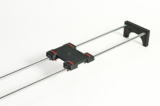
If you saw my post about a Motorized Camera Slider, this is a bit of an update, but it’s really more about the process than the end product, so if you’re interested in that, read on!

Slider End (Original)

I was originally using the improved camera slider V2 from our pal Marcus, and it worked well enough, but I wanted something different, so I tweaked what he had.

Slider End sliced

Marcus created his original file (I think) with Alibre Design, and since I couldn’t open it, I just worked with the STL file he provided. I loaded that into OpenSCAD and grabbed a slice of it using this method.

Slider End outline

Once I had a line drawing of the original slider end, I could use it to make my own. I imported the DXF File into Inkscape, my standard for 2D (and 2.5D) illustration.

Slider End outline

In reality, the only parts I really used from the original were the approximate size of the piece, and the two holes for the rods. I could have measured things, but loading up a file as a template was easier. I guess I could have got all fancy at this point, but I just kept it simple.

New Slider End

Once I had my SVG done in Inkscape, and exported a DXF file, it was a matter of doing the old linear_extrude method, like I did for my snowflakes, etc. I saved out an STL file and I was ready to print.

Nw Slider End

Here’s what the final piece looks like. One of the issues I had with the design Marcus created was that the rods only went part way into the plastic. There were screw holes to tighten down some screws onto the rods to hold things in place, but I never put any in. They might have also helped with the twisting issue this design has, but I may explore the idea of a two-piece design that clamps tight with the plastic. Or not… the nice thing is, it’s easy to experiment.

If I wanted to, I could probably make these ends out of wood, which would require just a drill press, or maybe out of a nice heavy metal, which might require drilling, or maybe milling. Both processes are a little messy, potentially more expensive, and require equipment you might not have. The nice thing about 3D printing these is that I can iterate a design quickly, and at a very low cost. I can even make them mostly hollow to save on time and materials during testing, and then make stronger, more solid versions when desired.

Nw Slider End

You may notice the carriage has some zip ties on it. Those are holding the LM8UU linear bearings in place. My original carriage was way too stiff, and without exact alignment (which you may not get with DIY plastic parts) it didn’t slide without some binding. The bearings were 58 cents each (I got a 10-pack from an ebay seller.) The bearings are a little noisy, so if you plan to shoot video with sound, you might have some issues. (Maybe more expensive bearing would make less noise?) As for the rods, they were about $15 each (pricey compared to the other parts) from VXB.com. There are cheaper alternatives depending on length, size, quality, etc. I went with 8mm because those are standard RepRap sizes.

At some point I may play with carriage designs as well. I actually did an early version that used felt instead of linear bearings (another trick from the RepRap world) which makes things cheaper and quieter, which may be desirable in some cases. And of course, I need to revisit the whole “motorized” part of this thing.

Until next time!

Categories
Uncategorized

I heard you like cameras…

GoPro Mount

Yo dawg, I heard you like cameras, so I put a camera on your camera so you can take pictures of taking pictures…

Occasionally 3D printing is accused of being useless, or worse, silly. Well this is anything but silly, and it’s certainly not useless.

GoPro Mount

By combining the hot shoe mount I recently printed along with this Female GoProHD Mount we’ve got the camera-on-a-camera thing down like nobody’s business.

GoPro Mount

So yeah, camera on camera action, courtesy of 3D printing. Yeehaw.

But seriously folks, one of the great things about open 3D printing is that combos and mashups are quite common, and since we’ve first jammed a piece of chocolate into a hunk of peanut butter, sometimes things just go better together.