You may remember the Matte Box Flags that I laser cut a while back, or the more recent LCD Arm that I 3D printed, well, there’s another accessory done now, and it took months and months to get it done. (Well, most of those months were due to procrastin—I mean, working on other projects.)
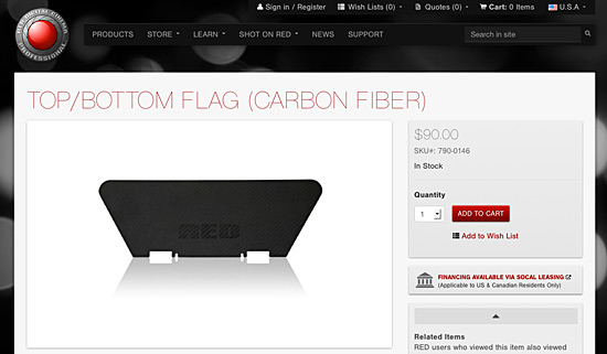
So our story begins with the RED Matte Box, which fits fine on the RED Lens, but when you slap a Zeiss Super Speed in place, the Matte Box can’t attach to it, no worries, RED sells two parts to solve your problem.


Just drop $350 USD on two parts and you can now secure your matte box to the 19mm rods. This is an ideal solution, but as you know, I’m cheap, and I’m DIY, so away we go!

Here’s how it looks underneath. Those two piece attach together and let the matte box ride the rails, and there’s some latitude for adjusting the height of things. It’s nice hardware, for sure.

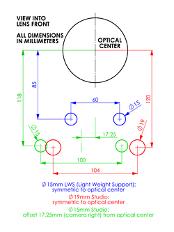
Once again I commend RED on publishing nice photos of their products…

…because it’s fairly easy to clean these up and trace them and create 2D profiles that can be extruded to 2.5D designs.

That’s much better! In fact, since it’s 2D I actually laser cut some wood to do a test fitting, since my 3D Printer was down for a bit when I was working on this.

(It was a nice diversion, and honestly I just really like laser cutting things.)
Somewhere along the way though, I pretty much abandoned the idea of recreating the stuff RED has and figured I should just design my own. Maybe after the whole RED Arm debacle I realized their designs are sometimes lacking…
Anyway, I was overly complicating things, so I decided to go simple. Also, we’re 3D Printing here!
Also, if making any rod-related things, I highly recommend you grab the Rod Standard Graph PDF from the OConor site.

This is what I eventually came up with. It’s mostly an extruded shape, but it does have some holes for the bolts including bits to lock in the hex heads, just like the Arm does. I wish I could say I just 3D printed this and that was it, but it’s far from it.
While I was working on this I was also working on calibrating the RepRap after the recent repairs, so I had a bunch of issues with things not printing as well as they should, or not exactly the right size, you know, like a 19mm hole printing at 18.673mm or 21.298mm. So I moved back to a bit of prototyping.

I used the old STL to DXF trick (thought slightly modified) to create a 2D design from the original 3D file. Once I had a DXF file I could use the Silhouette Cameo to easily cut some thick paper to get an idea of size and dimensions. Eventually I was happy with how things were looking so I moved on to plastic.

Here’s the DXF file extruded to 5mm tall, with the idea being that I could print this much more quickly (and with less plastic!) that doing the full print which is 25mm tall. This worked well, and I was able to test fit it on the rods, but I was still having a few weird issues with the 19mm hole sizing.

I ended up pulling my 5mm STL file into OpenSCAD and doing a difference to subtract most of it and just leave a portion so I could print this and test the hole sizing even faster. This too worked quite well.
This all might seem like a crapload of work to get what I wanted, but there was much exploring and learning along the way, and believe it or not, that’s most of the fun in doing it for me. If I just downloaded and printed something, well, that’s good if you want a thing, but not as good if you want to learn the process of creating a thing.

The final piece, with two 1/4″ hex bolts, some nut knobs (as seen previously), and two smaller screws and wing nuts to hold the matte box in place. There was a little bit of delamination in this print. I may try it on the LulzBot TAZ 3 that we just got in at Milwaukee Makerspace, as I think it will be a good test.

Hey, it works! It fits on the rods and holds the matte box in place. Simple enough, right?