
We’ve got a project at Brinn Labs where we need to bend some 16 gauge wire. The wire bends very easily, in fact, too easily, and you can bend it by hand, but you can’t really get nice curves. I looked up “wire benders” and found “fret benders” which people use to curve the frets for guitar building.

So I found this video titled DIY FRET BENDER – $5 USD FRET BENDER and I was in such a hurry I didn’t even realize the guy provided a bunch of design files! I guess I just often assume people don’t supply files, so I took a screen shot of the design and then dropped it into Inkscape and…

I just whipped up my own design quickly. Since I didn’t want to screw around with using the CNC machine for this, I just exported the DXF and extruded it in OpenSCAD so I could create an STL file suitable for 3D printing. Since there’s a slot and not just holes, it’s not the most fun thing to make with a drill press. Typically slots require a bit more work than holes, with filing and other time consuming hand tool work that is often best left to machines…

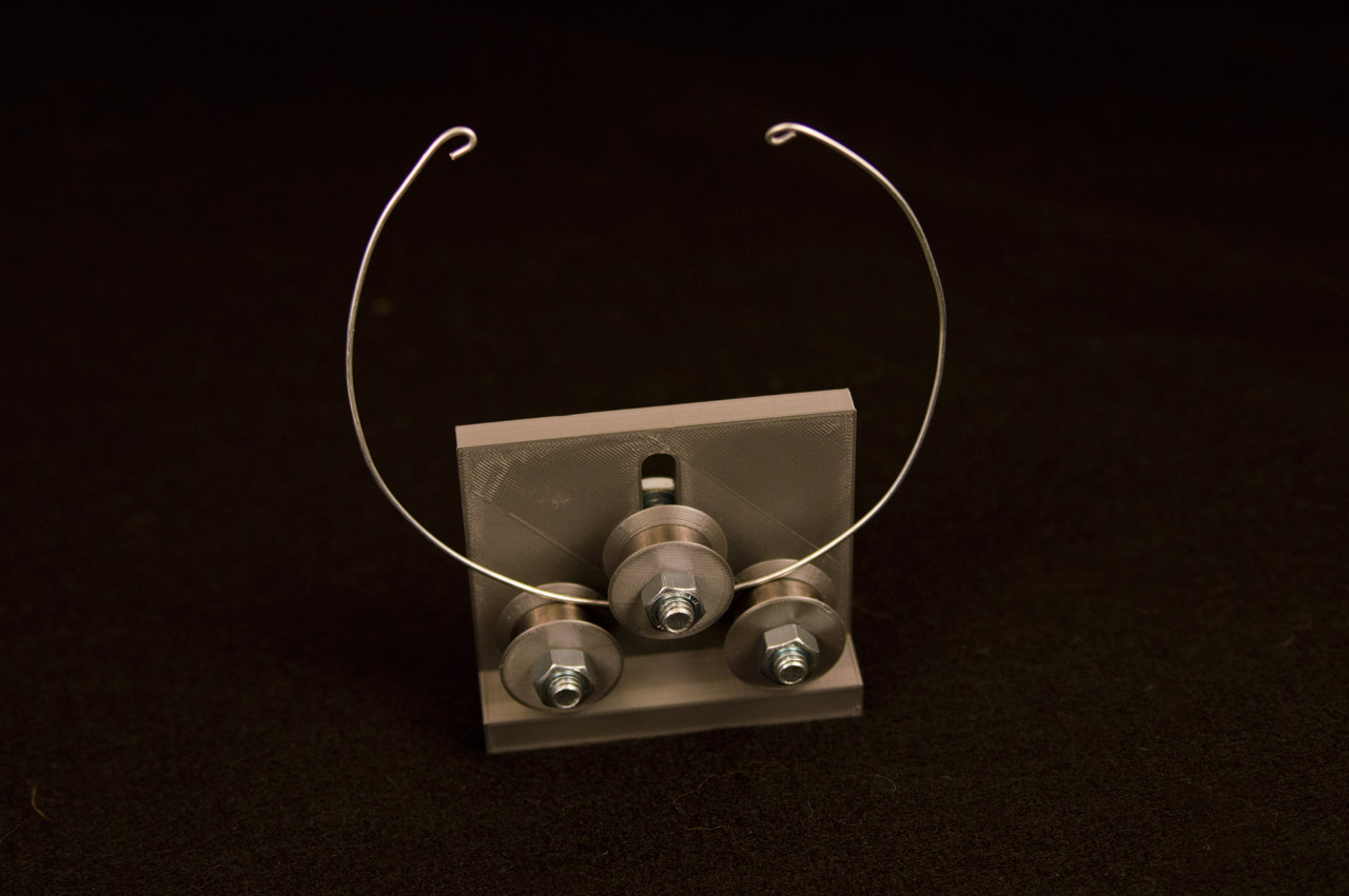
I designed three parts, and then printed the body and three spacers and six guides. You’ll notice a small lip on the guide piece. That’s to just touch the inside of the bearing so they can roll smoothly. The bearings? Yeah, tear apart that fidget spinner! We’ll need three bearings.

We’ll also need three 5/16″ bolts and nuts, though you could certainly use 8mm if you’ve got those handy. Hey, look, we’ve now got a wire bender!

There’s a little room for improvement on this version… The slot could be a little narrower, and I’ve found that without pliers it’s a bit difficult to tighten the nut. I fixed that by 3D printing some nut knobs so it can easily be tightened by hand. (I already had my own nut knob design file, but you can find plenty on Thingiverse.) No photo because I added it later. :/

This was a really simple build, and since fret benders often cost $50 to $100 (though I saw one for $25 on eBay) this was pretty dirt cheap. I don’t know if it’s up to the task of bending frets, but it should work fine for the wires we need to bend.

If I get around to it I’ll clean up the files and release them. You never know when you might need to bend some wire!


