Categories
Uncategorized

Bike Light – Downtube – White LED Strip

I’ve previously posted about a bike light I made and while I am working on a more complex, programmable, and controllable set of lights, I needed something quick because it got pretty dark last week. I found this LED strip in the shop, which I think I got from the junk-pile at work. It may have been an under cabinet style light… I don’t know or remember, but I do know it has a Micro USB port and runs just fine from a USB power bank.

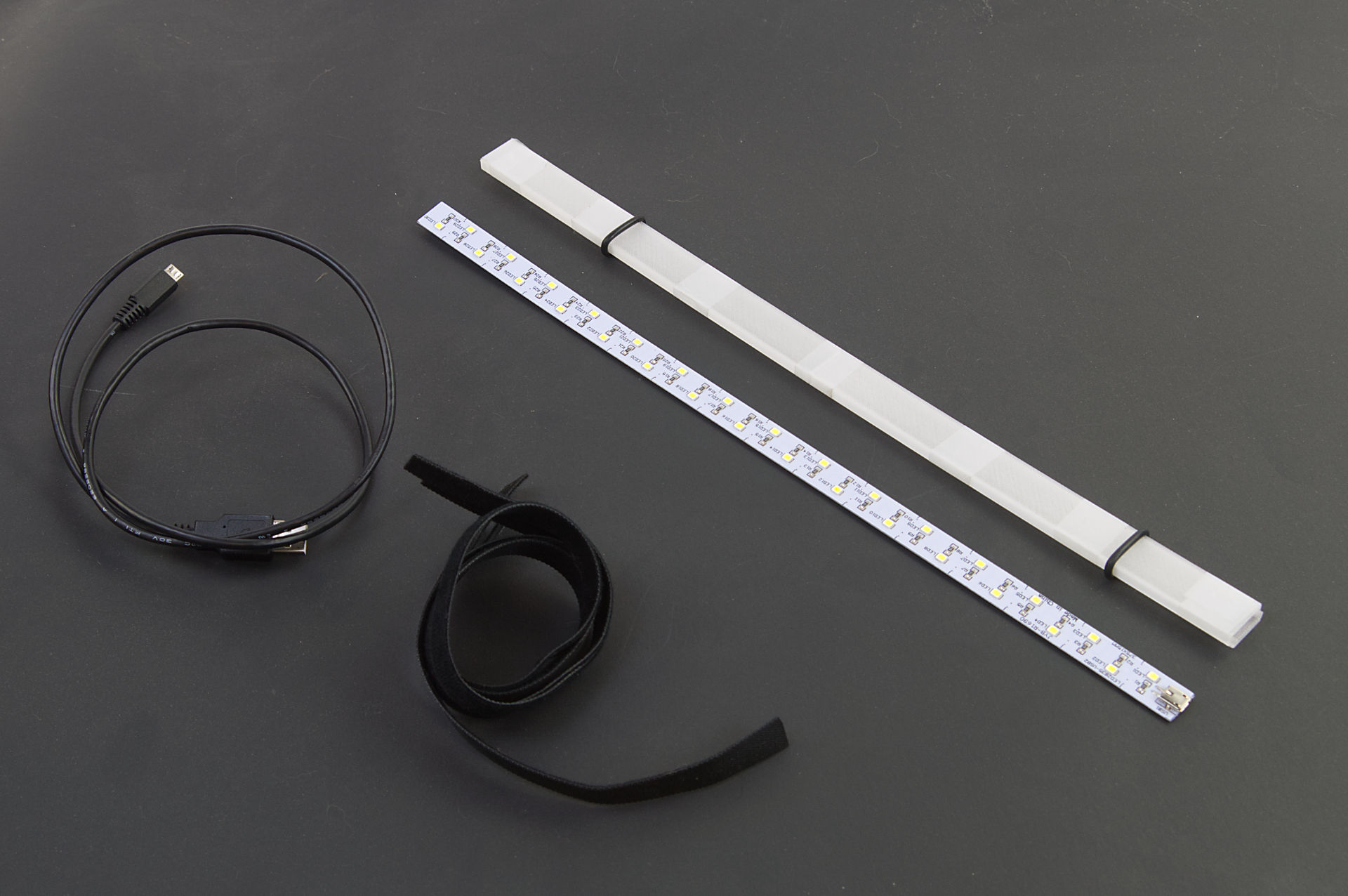
You can see the bare LED strip in the photo above… that’s how I found it. I was able to 3D print a sleeve for it to slide into. The Micro USB port is just at the end, and it’s not exactly waterproof, but I could just hot glue the heck out of everything if needed.

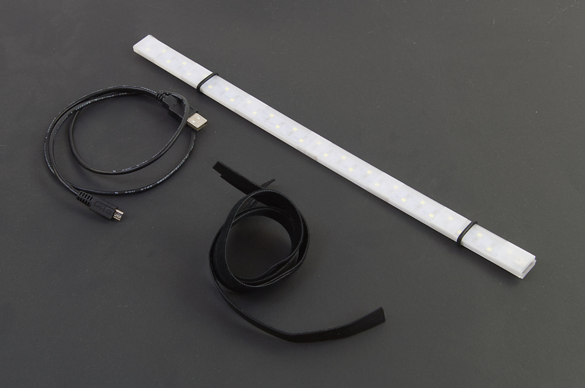
Besides the strip and 3D printed parts, there’s a 3 foot long Micro USB cable and some hook & loop straps. (I got a roll of 1/2in x 100ft Hook and Loop which someone said might be a lifetime supply.) There are also a few O-rings holding things together and they sort of work to help hold the strip in place on the bike. (I got a cheap O-ring set years ago.)

The 3D printed parts are taped together with clear tape, but Silicone Rubber Bands could also work.

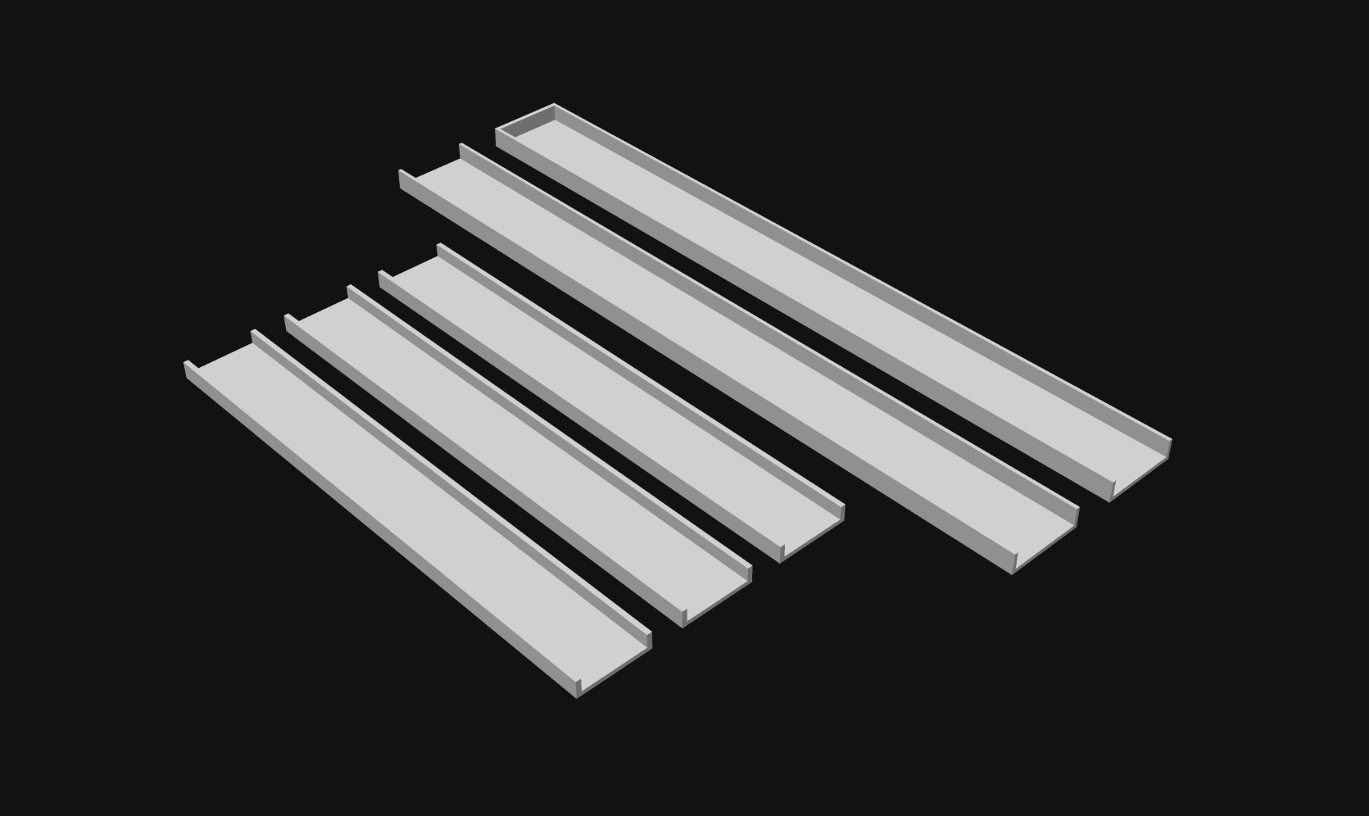
I designed the sleeve / sheath thing in 5 parts. Two “outside” pieces and three “inside” pieces. I figured two and three would be good so the seams between the inside and outside parts didn’t all line up.

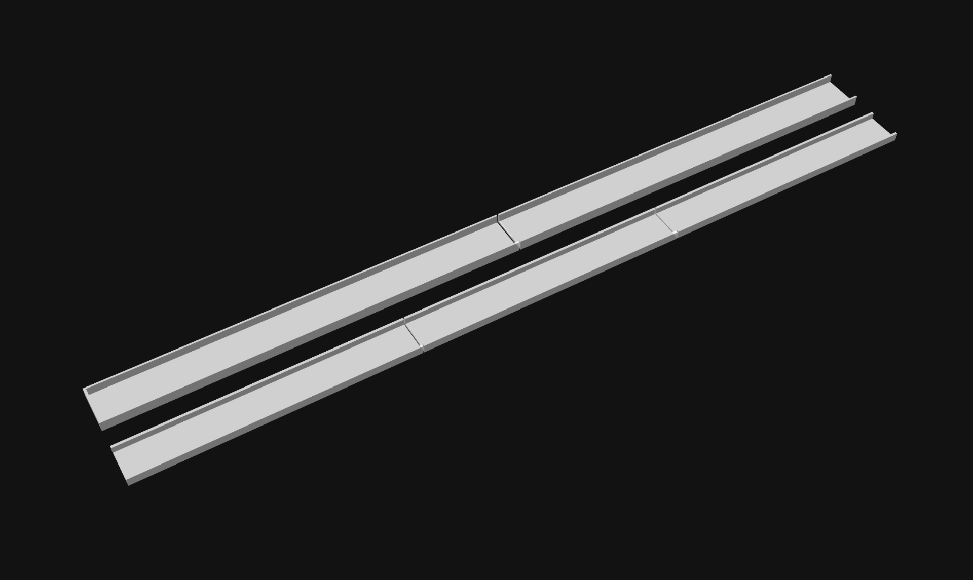
And here is what the pieces look like laid out so they are the length of the LED strip. I printed these with transparent PLA, which isn’t exactly clear, but it’s a thin print and the light shines through just fine.

If I were to make another one of these I’d probably use some COB LEDs. I’ve used these White 6000K LEDs bu you can also find cheaper COB LEDs. COBs are pretty bright, and some of them are also (mostly) waterproof.

To power the LEDs I have a USB power bank in my handlebar bag which I already use to charge my phone, so I just plug it into there.

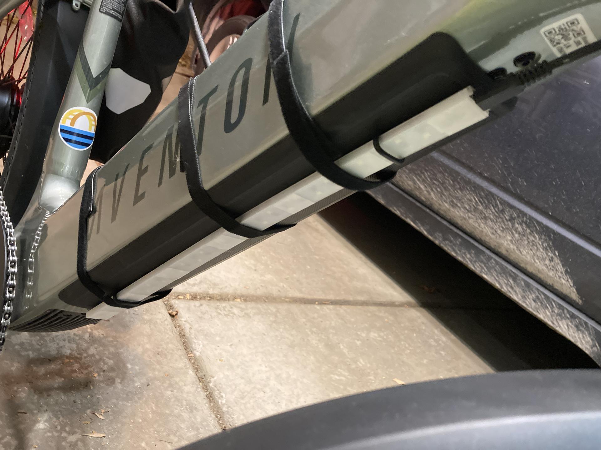
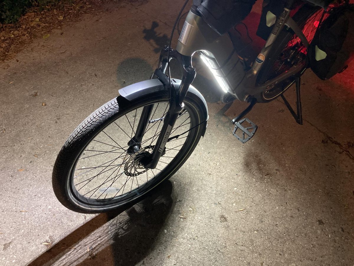
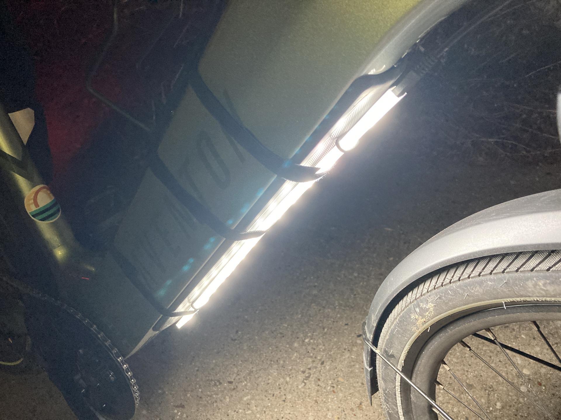
Here’s how I attach it to the downtube of the bike, which is where the battery is. The one little thing is that the strip could be about 3cm shorter and then I wouldn’t have to slide the whole strip up a bit to get to the charge port. (Maybe that’s a reason to make a new COB version?)

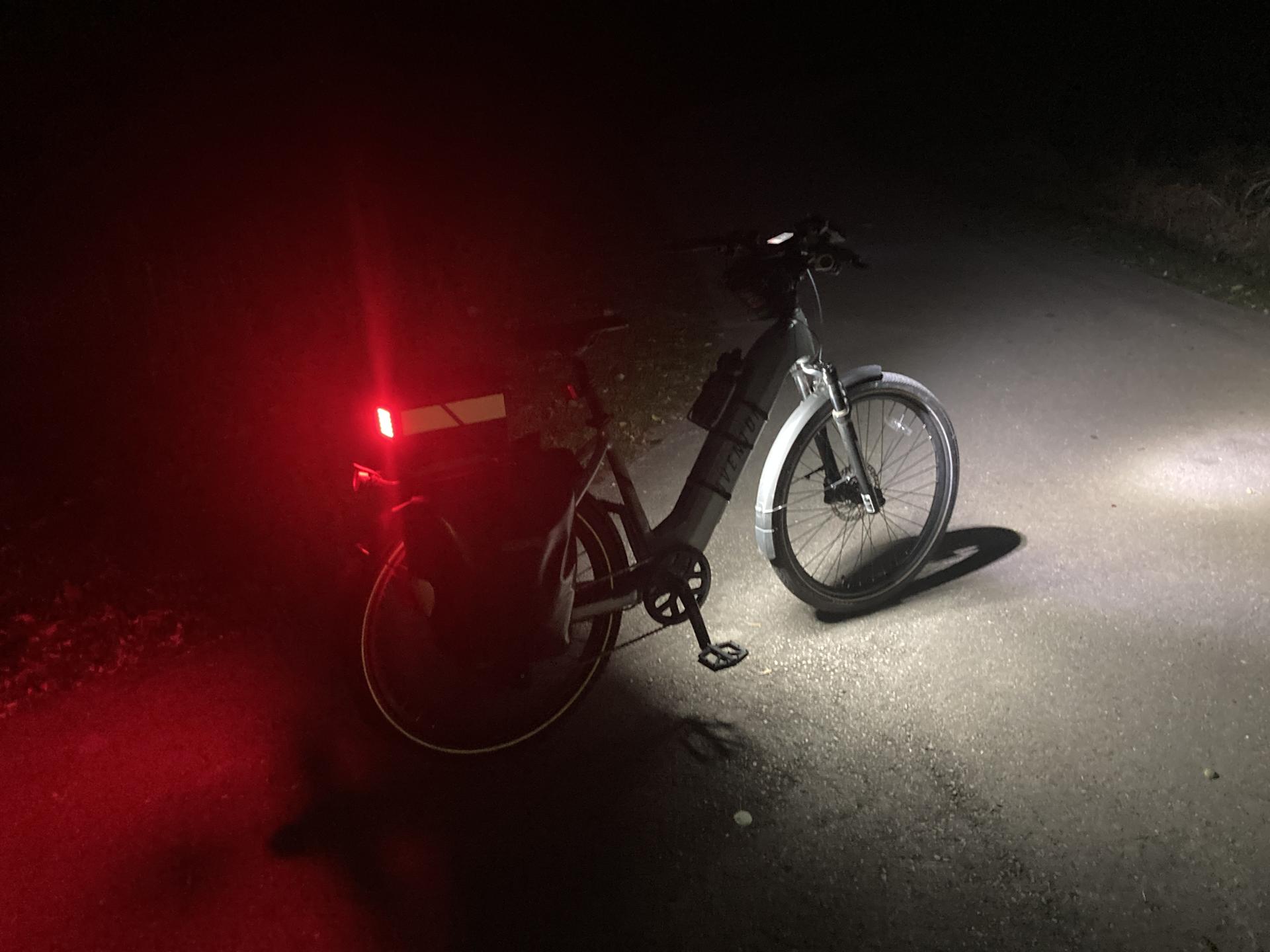
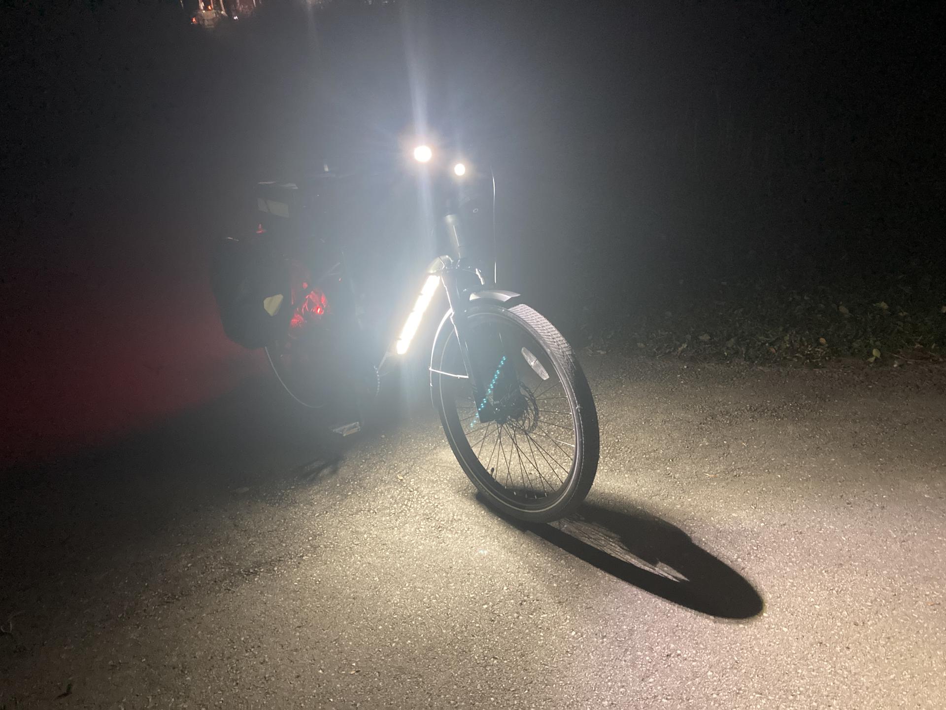
But hey, I think it works well! The above photo was taken on the Oak Leaf Trail, where there are no lights around, so it’s pretty much pitch dark there. The light definitely lights up the ground below and in front of the bike!

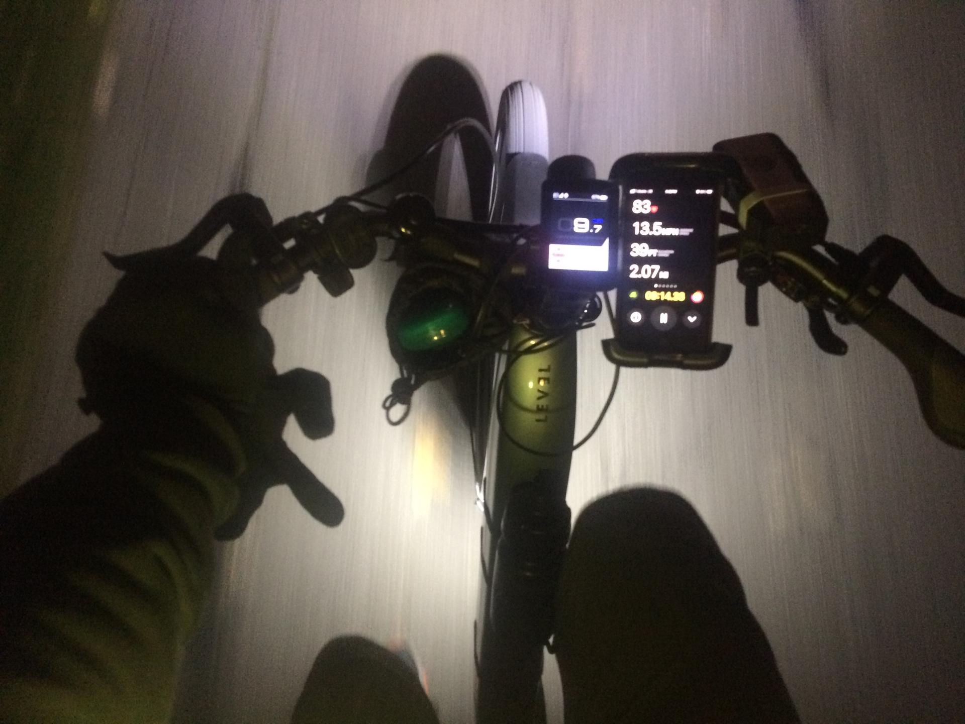
I commute home at 5pm and this time of year it is… dark. So anything I can do to light up me, the bike, the road, etc. and hope that drivers can see me is a good thing.

Many of the COB LED strips are just plain white (especially the cheap ones) but taking a note from Ryan it would be easy to 3D print a sleeve with colored filament to make lights a specific color. (And yes, I have one of Ryan’s lights! I just need to find the time to install it.)

Note: Well, I managed to find my extra strip of COB LEDs and it’s actually got an 18″ long USB cable built into it. So making another one of these lights would be pretty darn simple… I might just do that since it would fix the 3cm issue I mentioned above.

Hey! It also looks like you can cut COB strips! So by cutting a COB strip I could make a shorter strip, a wider strip, etc. so yeah… I’ve got a few ideas now!

Categories
Uncategorized

Giant LED Cube

You know when you mean to do something and then forgot and a few years pass? Okay then… I wrote the post Designing a Giant LED Cube in 2018 and hey, it’s time for the next post!

Anyway, I built what was (jokingly) call the “World’s Largest LED Cube!” but eventually settled on “Giant LED Cube” and here are some photos and videos showing it off. And yes, since it uses “LED Bulbs” I consider it an LED Cube. It’s not technically a “cube” because it’s a bit taller in the Z direction but hey, close enough!

To connect all the PCV pipes together I got eight 3-Way Elbows, twelve 4-Way Tees, eight 5-Way Crosses… and 27 Elbows, 28 Tees and a ton of PVC pipe, obviously!

The LED Cube was shown at Maker Faire Milwaukee in 2018 and 2019, as well as the Fall Experiment in 2019, The Elkhorn Mini Maker Faire in 2019, and the Madison Mini Maker Faire in 2019. Sadly at the end of 2019 the department I worked for got shut down and I was left with just the control box, the electronics, and the PVC connectors, as I didn’t have space for all the PVC pipes, though I did get some (not all) of them later on and thought about building a smaller version of the cube but life stuff happened in 2020. Sigh…

While this was a large sculpture (the largest I ever worked on) it was fairly easy to put up and take down, and could fit in a reasonably sized vehicle like a van, small truck, or even a Honda Element. the 5 foot pieces of PVC pipe did take up some room but 5 feet isn’t too unwieldy to deal with. All the other stuff fit in a few bins.


Note: This post may contain Affiliate Links. Read More.

Categories
Uncategorized

The LED Burns Bright

Disclaimer: I have destroyed light emitting diodes (LEDs) in the past. Typically on purpose, by feeding them too much voltage until they burn out in a bright flash. It’s fun to do if you’ve got a variable power supply with a dial and can slowing crank up the voltage.

That said, this is about trying to destroy an LED without trying to destroy and LED. (Or maybe, trying to not destroy an LED but still breaking the rules.)

The rules you say? Yes. As in, you need a resistor when connecting an LED to an Arduino. This is just, like, a fact. You can get away with putting a resistor-less LED on an Arduino for testing, or learning, or a quick demo, but to do it right, always add an appropriate resistor inline.

There’s a web site called LEDCalc.com that helps you determine the appropriate resistor for the LED and voltage you are using. Tell it you’ve got 5 volts, one LED with a voltage drop of 2.0 volts, and want to give it 20 milliamps and it will tell you to use a 180 ohm resistor. (There’s fancy maths to figure this out as well, but I’m an artist who does not excel in maths.)

In the photo above you’ll see a (very bright) yellow LED connected to an Arduino Nano. (This Nano specifically is manufactured by Elegoo.) I have no resistor in my circuit, I have nothing else connected, just a single LED on a single pin, with a digital write to turn it on at full power. (As it were.)

Okay, so at some point the LED will be destroyed, or the pin on the Arduino will be destroyed, or the Arduino itself will be destroyed, or some component will fail. But… when will that happen? I’m a week into this experiment, and so far, all is well. Will it take a month, a year, a decade? Is the time to failure completely unknown, and completely random. Is it pure luck that this works, and it could fail any second now? Do I need to blink it on and off to get an inrush of current to the LED to stress it more?

I found this Arduino MEGA with 27 LEDs connected to 27 different pins, which I used for testing, and it seems fine as well. Granted, I don’t have all LEDs on at the same time for any real length of time. It’s a blinkenlights thing so lots of off time and some on time.

I’m now really tempted to change the code so it just turns on all 27 LEDs at once for an extended amount of time. I’m a bit curious about this whole thing now. I understand the reasoning behind current limiting resistors, but I’m wondering how that comes into play in the real world. One of the trickiest things I’ve dealt with when designing circuits is that they should work, they work on paper (or on the screen) but in the real world something goes wrong. EMF, physics, gremlins… whatever. Something you don’t expect comes along and screws things up… But this seems like the opposite, where we plan for what should/could go wrong, but then it doesn’t.

I probably need an actual Electrical Engineer to walk me through this one…

Categories
Uncategorized

Manual Crankable Larson Scanner

The most recent fun project at Brown Dog Gadgets is our take on the classic Larson Scanner. EMSL has an awesome kit, and many people who have experimented with an Arduino and LEDs have made a breadboard version.

Well, Josh and I made a LEGO version using Crazy Circuits parts, and instead of a microncontroller it’s controlled by a hand crank! Yeah, it’s an Analog, Hand-Cranked, LEGO-Based, Crazy Circuits Larson Scanner.

As with all of our projects, the instructions, files, templates and all that are available for free. Check it out! You can certainly use other components besides Crazy Circuits and Maker Tape for this, but as always, getting parts from us (or a reseller) ensures we can keep producing open source educational content and curriculum. And yes, schools, teachers, maker clubs, and other use these resources, and we incorporate their feedback into new designs and projects.

There’s a bit of an explanation about the cylinder and “coding” as it were, in the instructions. While this is a simple & fun project, you can expand upon the basic concept to talk about more advanced concepts. That’s pretty much our goal with these things.

Josh had a lot of fun making the video for this one, though I’ve heard that stock music way too many times in other videos! ;)

Perfect for your Knight Industries Two Thousand or Cylon!

Categories
Uncategorized

Designing a Giant LED Cube

giant-led-cube-02

This year my “big” project for Maker Faire Milwaukee was a Giant LED Cube. In this post I’ll talk about designing it, and in a follow up post I’ll talk about building it.

I should mention that the idea for this started maybe three years ago. I think it was during a meeting for Maker Faire at Milwaukee Makerspace and I tossed out the idea of building a giant light sculpture using light bulbs. Lance and Chris talked about it a bit and Tom started looking up parts on Alibaba. Nothing came of it that year, and I sort of forgot about it for a while. In fact, I really didn’t think about it again until after we completed the DecaLight last year. Once the two dimensional relay controlled light bulb thing was done I thought going three dimensional would be a good idea.

I modeled the cube in OpenSCAD, and then animated it just for fun. I figured out how many pieces of each PVC joint I would need, and while I originally thought a 20′ cube would be a good idea, after some initial tests (and the unavailability of 10′ PVC pipe) I ended up going with a 10′ cube so the 5′ PVC pipe I could get would work.

I picked up Jordan Bunker’s book PVC and Pipe Engineer: Put Together Cool, Easy, Maker-Friendly Stuff last year and then ended up learning about FORMUFIT which allows you to build furniture using PVC pipe. I had a plan!

giant-led-cube-01

Here’s the first sketch of the Giant LED Cube. By now I had decided that I would use LED light bulbs and standard household lamp sockets. The nice thing about using such common parts is that they are very cheap. I found these Black Bakelite Fixture Socket with Terminals and ordered some so I could test the fit. It was close enough that it would work, and I just needed to make a small adapter. Well, at least 27 small adapters.

giant-led-cube-04

I designed and 3D printed over 30 of these using clear ABS, which is remarkably close to being white, and since you wouldn’t really see them, I was fine with the close match. I cranked these out so I’d be ready when they were needed. Like many parts of this project, they are just press fit into place. The entire thing was designed to be easily assembled and disassembled for making transport and storage an simple affair.

giant-led-cube-03

I had the basic design of the cube figured out, so I decided to work on the controller. Since we’d have 27 LED light bulbs I decided to use an Arduino Mega, which had plenty of I/O pins, along with two 16 channel relay boards. LED light bulbs are pretty lower power (compared to incandescent bulbs, anyway) so even though they’re 110 volts AC, 27 bulbs all on at the same time probably pulled less than 6 amps.

The image above represents my first attempt at layout out the controller, which I eventually abandoned. The screw terminals ended up not being a good idea. I would be pretty busy running Maker Faire so I assumed that I could find helpers able to strip wire, put them into the screw terminals, and get it all right. After attempting this myself on a small scale I decided that it needed to be even simpler, and clear enough that almost anyone could do the setup. So I scrapped the screw terminals. Around this time I also decided that running all of the power cords inside the PVC was going to be tedious and difficult, so with the decision to just run the cords on the outside (at least for this installation) I decided to just use standard household plugs. This would allow nearly anyone to just match up some numbers and plug things in. Simple wins!

The design process for the Giant LED Cube wasn’t too difficult. Doing this like this (designing, specifying parts, building, etc.) is pretty much my day job. The wiring was definitely tedious, and required at least one unexpected hour-long troubleshooting session due to a bad connection. I had a lot of help with the wiring of the lights from Adrian, and a lot of help with initial assembly from Becky. Without their help things would have taken me a lot longer. (Thank You!)

I think I’ve spewed enough about this project for one post (which I wanted to get out last month!) so I’ll end it here and get working on Part II ASAP.