You know when you mean to do something and then forgot and a few years pass? Okay then… I wrote the post Designing a Giant LED Cube in 2018 and hey, it’s time for the next post!
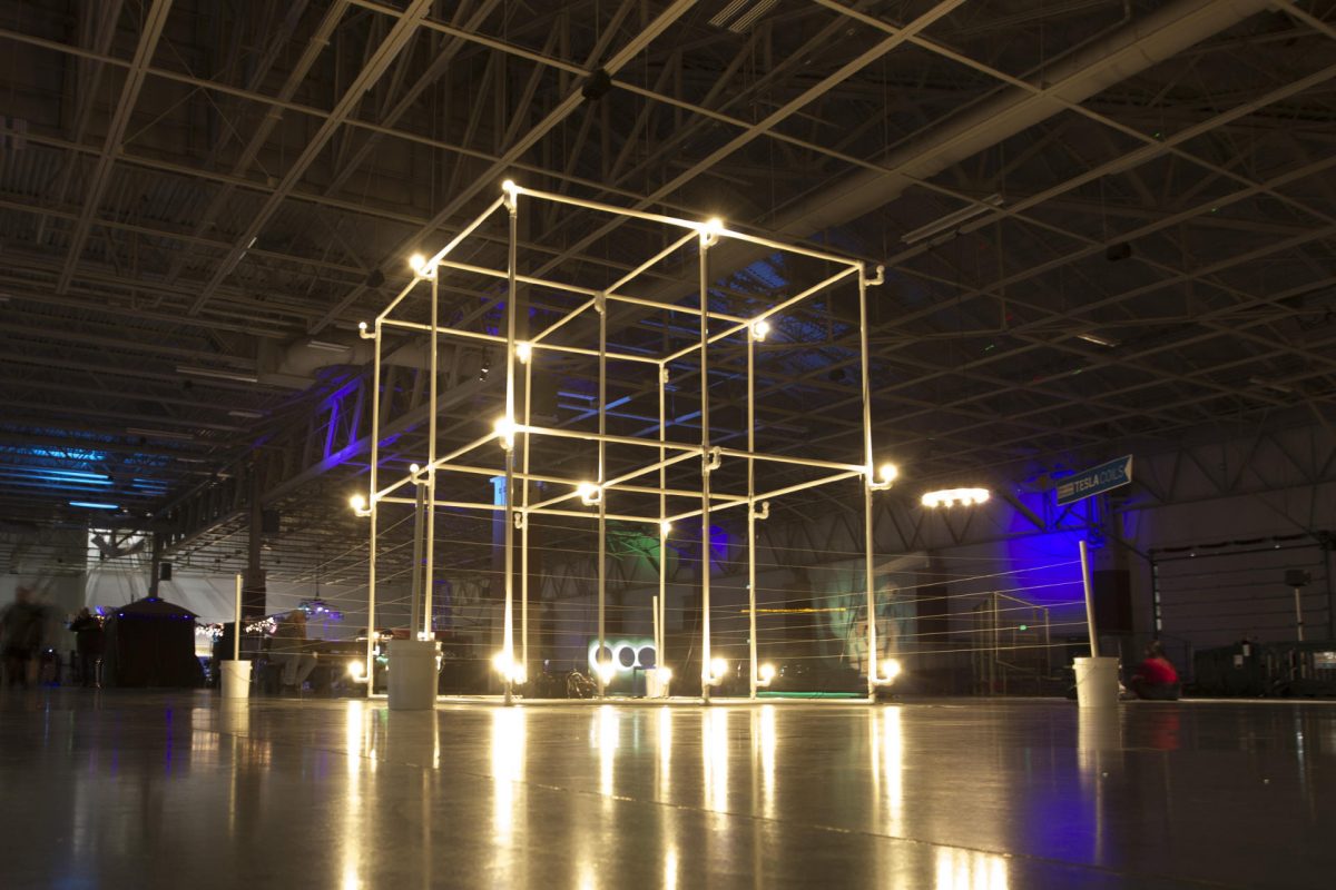
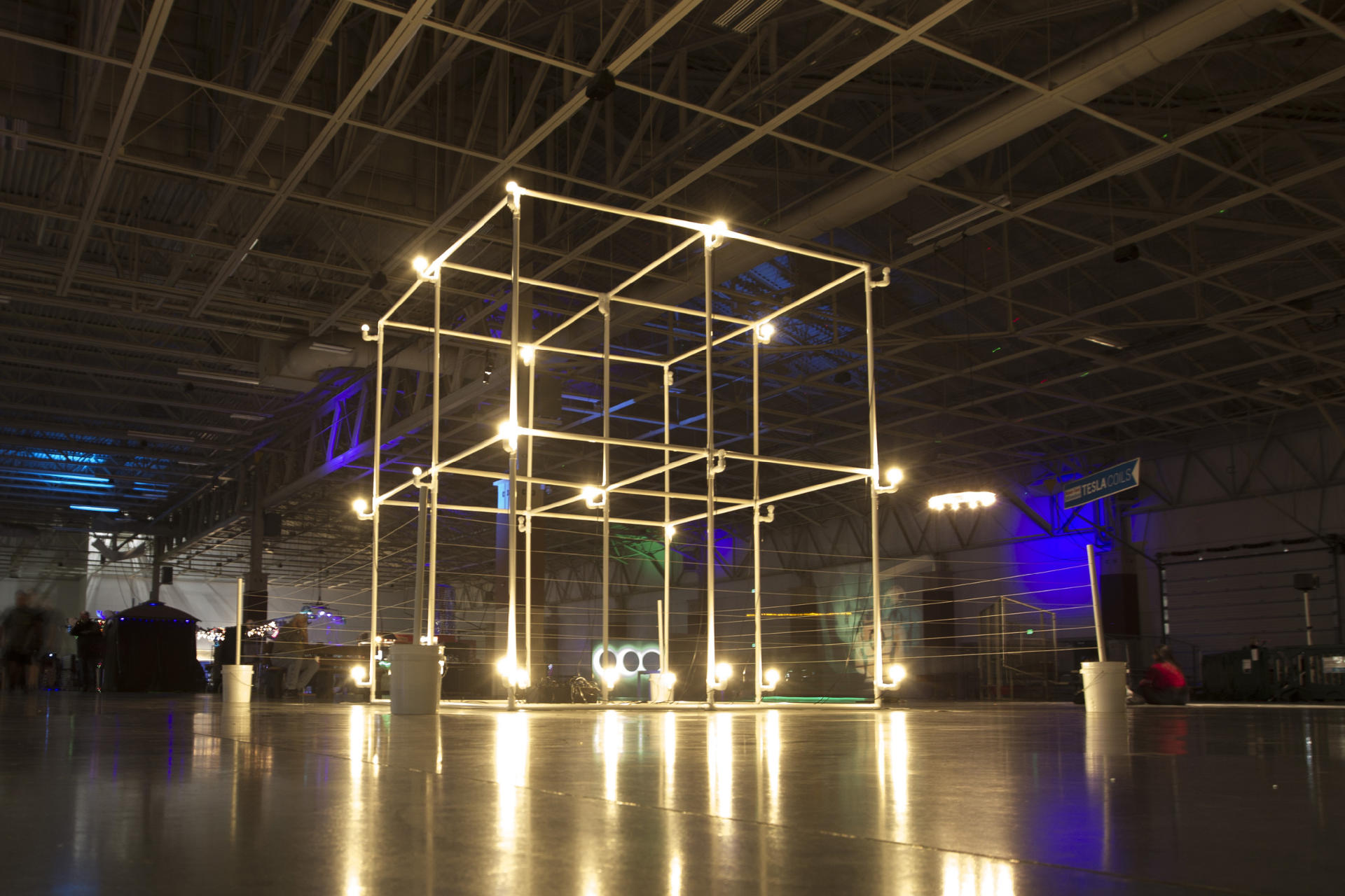
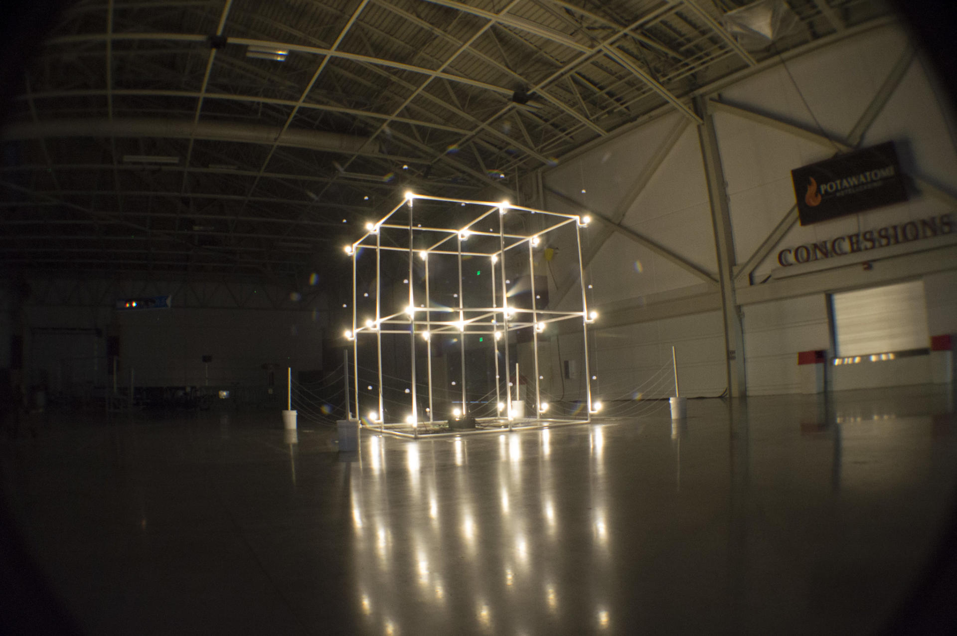
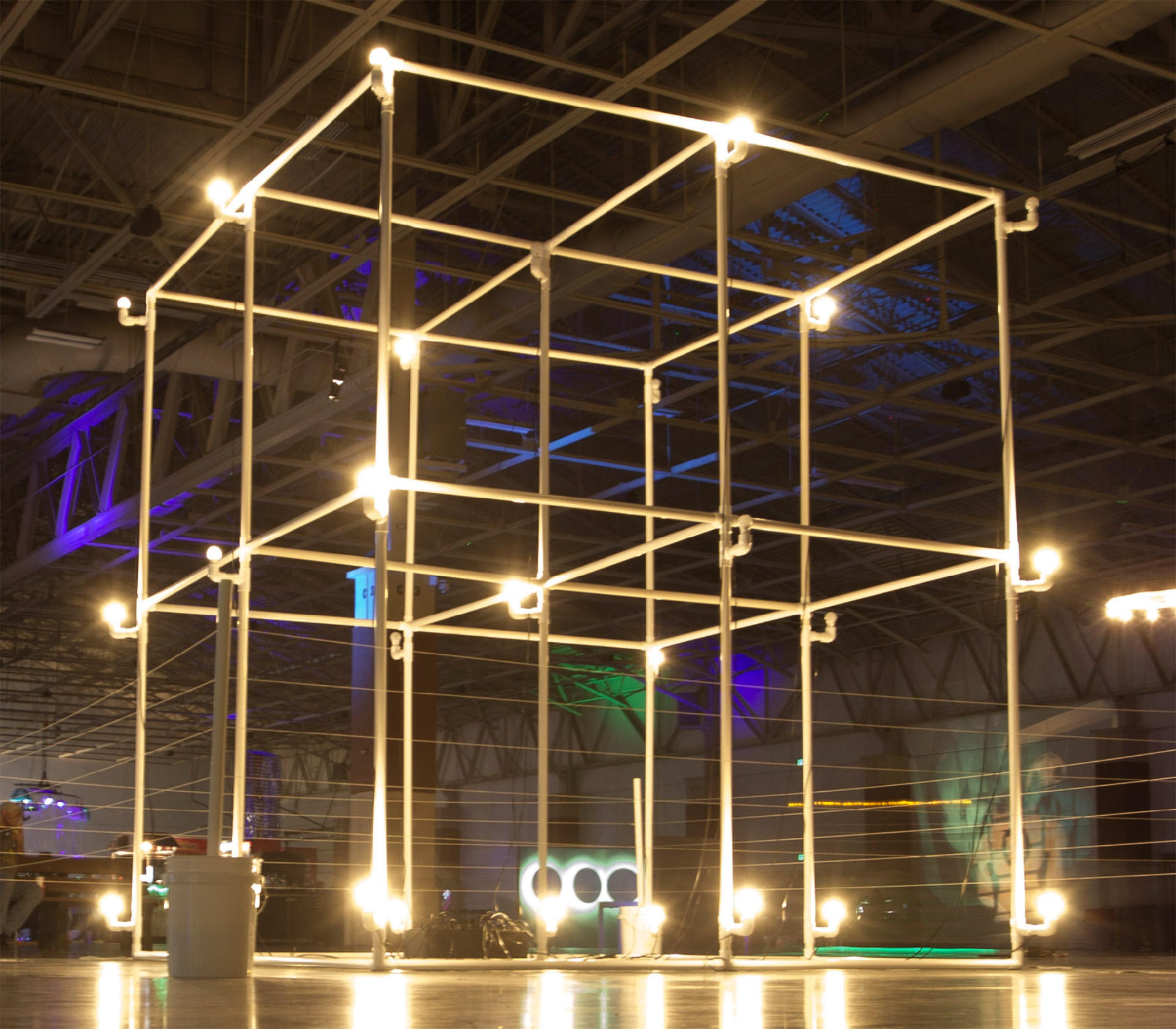
Anyway, I built what was (jokingly) call the “World’s Largest LED Cube!” but eventually settled on “Giant LED Cube” and here are some photos and videos showing it off. And yes, since it uses “LED Bulbs” I consider it an LED Cube. It’s not technically a “cube” because it’s a bit taller in the Z direction but hey, close enough!
The LED Cube was shown at Maker Faire Milwaukee in 2018 and 2019, as well as the Fall Experiment in 2019, The Elkhorn Mini Maker Faire in 2019, and the Madison Mini Maker Faire in 2019. Sadly at the end of 2019 the department I worked for got shut down and I was left with just the control box, the electronics, and the PVC connectors, as I didn’t have space for all the PVC pipes, though I did get some (not all) of them later on and thought about building a smaller version of the cube but life stuff happened in 2020. Sigh…
While this was a large sculpture (the largest I ever worked on) it was fairly easy to put up and take down, and could fit in a reasonably sized vehicle like a van, small truck, or even a Honda Element. the 5 foot pieces of PVC pipe did take up some room but 5 feet isn’t too unwieldy to deal with. All the other stuff fit in a few bins.
Note: This post may contain Affiliate Links. Read More.
I honestly can’t remember where I got the idea to make a bunch of dodecahedrons for Maker Faire Milwaukee came from, but I do remember looking at Thingiverse for some connectors I could use with 1/4″ dowel rods. I know I tried Trammell Hudson’s design, since I always admire his work, but I was not using pencils, so it didn’t work. I did attempt to alter his file, but ultimately ended up designing my own file, which worked well enough that I wanted to share it. (Check out Dodecahedron Connector on PrusaPrinters.)
So I made nine dodecahedrons that could hang from the ceiling in the Dark Room. And since they’d be in the Dark Room I figured I should use fluorescent filament to create the connectors, and fluorescent paint to paint the wooden dowel rods, and with help from Kathy H. at Milwaukee Makerspace, we got everything painted. Sadly, we did not get the blacklights set up in the Dark Room due to budget constraints, and there was too much light where they were placed, and we had to bundle them all together, and… well, anyway, they turned out great, despite a few issues with presentation.
I’ve also made a smaller (hand-held) model for home. It’s small enough to fit on a 13″ MacBook Pro, though I might hang this one from the ceiling as well. Or maybe make it into a lampshade. I don’t know yet.
This is the original version, which uses 12″ long, 1/4″ diameter wooden dowel rods. A pack of 100 dowel rods is under $15, and a roll of fluorescent filament is about $22. Since you need 30 dowel rods and 20 connectors per dodecahedron you can easily build three large ones (or a lot of small ones) for under $40 USD as long as you’ve got access to a 3D printer.
This year my “big” project for Maker Faire Milwaukee was a Giant LED Cube. In this post I’ll talk about designing it, and in a follow up post I’ll talk about building it.
I should mention that the idea for this started maybe three years ago. I think it was during a meeting for Maker Faire at Milwaukee Makerspace and I tossed out the idea of building a giant light sculpture using light bulbs. Lance and Chris talked about it a bit and Tom started looking up parts on Alibaba. Nothing came of it that year, and I sort of forgot about it for a while. In fact, I really didn’t think about it again until after we completed the DecaLight last year. Once the two dimensional relay controlled light bulb thing was done I thought going three dimensional would be a good idea.
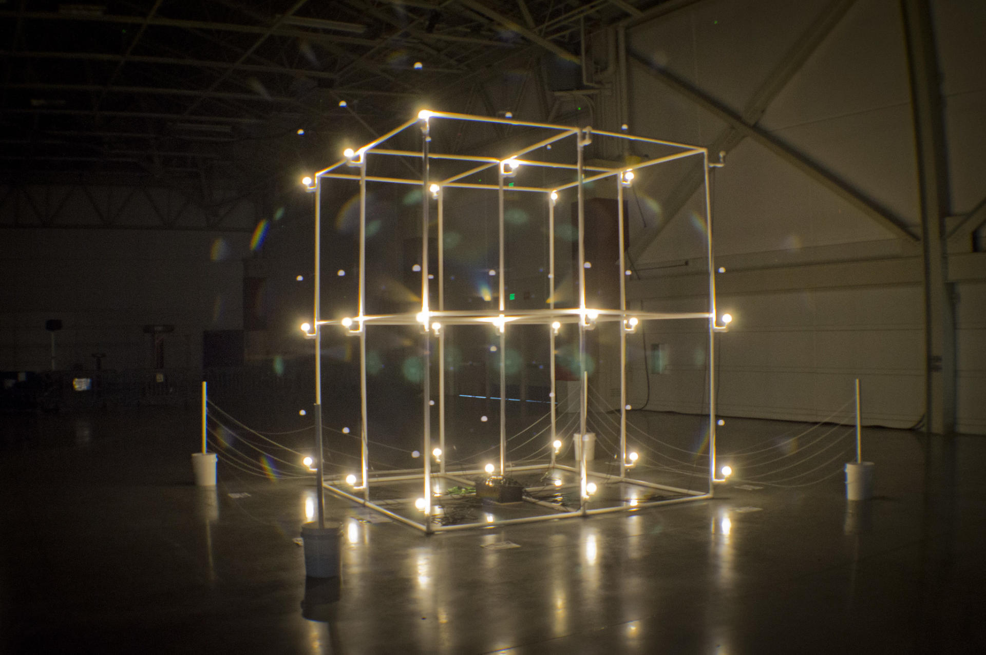
I modeled the cube in OpenSCAD, and then animated it just for fun. I figured out how many pieces of each PVC joint I would need, and while I originally thought a 20′ cube would be a good idea, after some initial tests (and the unavailability of 10′ PVC pipe) I ended up going with a 10′ cube so the 5′ PVC pipe I could get would work.
Here’s the first sketch of the Giant LED Cube. By now I had decided that I would use LED light bulbs and standard household lamp sockets. The nice thing about using such common parts is that they are very cheap. I found these Black Bakelite Fixture Socket with Terminals and ordered some so I could test the fit. It was close enough that it would work, and I just needed to make a small adapter. Well, at least 27 small adapters.
I designed and 3D printed over 30 of these using clear ABS, which is remarkably close to being white, and since you wouldn’t really see them, I was fine with the close match. I cranked these out so I’d be ready when they were needed. Like many parts of this project, they are just press fit into place. The entire thing was designed to be easily assembled and disassembled for making transport and storage an simple affair.
I had the basic design of the cube figured out, so I decided to work on the controller. Since we’d have 27 LED light bulbs I decided to use an Arduino Mega, which had plenty of I/O pins, along with two 16 channel relay boards. LED light bulbs are pretty lower power (compared to incandescent bulbs, anyway) so even though they’re 110 volts AC, 27 bulbs all on at the same time probably pulled less than 6 amps.
The image above represents my first attempt at layout out the controller, which I eventually abandoned. The screw terminals ended up not being a good idea. I would be pretty busy running Maker Faire so I assumed that I could find helpers able to strip wire, put them into the screw terminals, and get it all right. After attempting this myself on a small scale I decided that it needed to be even simpler, and clear enough that almost anyone could do the setup. So I scrapped the screw terminals. Around this time I also decided that running all of the power cords inside the PVC was going to be tedious and difficult, so with the decision to just run the cords on the outside (at least for this installation) I decided to just use standard household plugs. This would allow nearly anyone to just match up some numbers and plug things in. Simple wins!
The design process for the Giant LED Cube wasn’t too difficult. Doing this like this (designing, specifying parts, building, etc.) is pretty much my day job. The wiring was definitely tedious, and required at least one unexpected hour-long troubleshooting session due to a bad connection. I had a lot of help with the wiring of the lights from Adrian, and a lot of help with initial assembly from Becky. Without their help things would have taken me a lot longer. (Thank You!)
I think I’ve spewed enough about this project for one post (which I wanted to get out last month!) so I’ll end it here and get working on Part II ASAP.
It’s been a while since Decagon Light (Part II), but we’re here with Part III! Thanks to Jason we (mainly he) finally got around to do the CNC work for this monstrosity. Becky then wired it up while I worked on the programming. (Thanks, Brinn Labs!)
Besides adding some new patterns, I modified the code so you can use any consecutive pins. For the LEDs I use pins 1 through 10, but for the lamps we’re using 2 through 11. (Don’t ask why.) I also added an logic flipper, because LEDs and relays work opposite, HIGH is LOW and LOW is HIGH, depending on which you are using, so yeah, a lot of the code writing was just to deal with the differences between two version of this thing. Anyway, I squashed the last bug today, so it’s all good. (I think.)
And here’s a short video of it in operation. There’s still work to do, but we’ve made great progress in the last two weeks. (And yeah, I really wanted it done before Maker Faire, but didn’t quite hit that deadline.)
You’ll notice the design of the lines changed a bit. It’s still a decagon (a 10-sided polygon) but it’s no longer a 9-simplex. It’s almost a 5-orthoplex, but not quite. If you can figure out exactly what it is, let me know.
The inspiration came from something Kathy and I saw at Maker Faire Detroit. After seeing the “M” at the Henry Ford I remembered I had left over batteries, LEDs, and binder clips from the Learn to Solder kits I made for the Zoom Symposium at UWM.
I thought that since I had the leftover parts because of a UWM connection, I should find a way to get UWM involved again, so I persuaded my Physical Computing class to help. (And by “persuaded”, I mean I bribed my students into helping me with assembly of the piece.)
I didn’t have a piece of posterboard large enough to make the star I wanted, so I make five segments that could be assembled into a star.
Since I don’t have a printer capable of tabloid printing, I split the pieces into halves and printed on letter paper. Some assembly was required.
I cut the pieces and taped them together, and then had the “star legs” I needed. I then used it to cut the black posterboard using an X-ACTO knife and cork-backed steel edge ruler on a cutting mat. (Sorry, no laser!)
And yes… things didn’t fit right. Again, no laser. I trimmed edges a bit until things fit together right and it was deemed “good enough”.
I took the star pieces to Kenilworth and attached them to the piece of sheet metal with some magnets. At this point, I had to wait until the Thursday night right before Maker Faire, which luckily enough, is when I have class! I brought in some bags of candy, and while I taught students in groups of two or three how to solder, the rest of them assembled everything…
200+ pieces of black construction paper were cut for insulation, 200+ batteries were opened and had 200+ LEDs stuck onto them, 200+ binder clips had the clippy parts removed, and 200+ magnets were attached and then placed on the sheet metal. Things go fast with so many people helping!
Here’s the first test with the lights out, which we did during the DECODE meeting. It was impressive!
I then had to get Star-Blinken from the fifth floor of Kenilworth to my car, which was fun, because the Milwaukee Film event was setting up and Kenilworth was a bit crowded. The stand is heavy to prevent tipping, so I needed a cart. Also, since there’s no on/off switch, it blinks all the time. No control!
I loaded Star-Blinken into my car and yeah, it just kept on blinking! It was a fun ride home. It kept blinking strong all night long in the garage and then I unloaded it the next morning at Maker Faire. I ended up placing in at the entrance of the Dark Room, mainly because there weren’t other things there, but I think being in a darker area may have been even better. (I was a bit busy producing the event to worry about a better placement.)
Dana helped disassemble Star-Blinken at the Expo Center, and I asked her to just drop all the pieces into a box. After I loaded everything out and took it home, I forgot which box it was in and opening the box gave me a pleasant surprise. I then spent over an hour putting all the binder clips back together, and taking apart all the pieces.
The cost of this piece was approximately $100, and about $36 of that was for the batteries, which are the only parts that cannot be reused. (Well, actually, some of them have life left in them! Some did die though. None are at full power anymore.)
So I can reuse all the parts, except for the batteries, either in a similar piece in the future, or in the Learn to Solder kit. I may return the sheet metal to Tom from Milwaukee Makerspace, and the wood was disposed of. (The wood cost $0.00 as it was all scrap, and I reclaimed all the screws.)
This is just one post in a series, check out the other posts as well: