Categories
Uncategorized

REConnector PCB

This is definitely the smallest and simplest PCB I’ve ever designed. It’s 14.6mm x 7.9mm. That’s it.

But why!? Well, if you saw the last post about the Pin Bender, this is the second part… once those pins are straightened out, we put the lil PCB on there.

These rotary encoders come with right angle headers, and they work great in a breadboard, but I often have to solder wires to the rotary encoder PCB. I used to solder wires directly to the pins, and then heat shrink them on. That was terrible!

After that I desoldered the pins to get to the holes to solder on wires. That was also terrible!

I need to solder wires onto these things often enough that designing a Pin Bender and getting some PCBs fabricated totally made sense from a cost & time perspective. The PCBs are super cheap because they are so small. They serve a specific purpose, and that’s great.

Each board comes out just under 9 cents. (Not including shipping which was almost double that cost, but I ordered three different PCBs in one order.) It’s worth 9 cents on a BOM to me for the time it saves, so I consider it a win.

Categories
Uncategorized

More PCBWay Boards

I’ve been working on a number of projects the past few months, and many of them require custom printed circuit boards. A few weeks ago as I was finishing up the design of a new board I got an email from the crew at PCBWay. (You might remember that I had boards made by them a few years ago.)

As luck would have it I was just exporting some Gerber files so the timing was great! I got my boards created by PCBWay and they arrived about two weeks ago. It took me a bit of time to wrap other projects and get things soldered up and programmed, but the boards worked great. Often you don’t get PCBs right the first time, but luckily all my connections were fine (It’s a fairly simple board) but there are a few things I might want to change about the dimensions and the mounting holes.

I’ve been using this as a supplemental USB keyboard. For testing I’ve programmed it to be function keys F13 through F20 (which can then be assigned to key commands for certain applications, like OBS: Open Broadcaster Software.) I’ve also set it up as a MIDI device to trigger sound effects using my SoundProp application. It can also serve as a toggle for your mic and camera in videoconferencing software like Zoom, Google Meet, Microsoft Teams, etc. It’s pretty robust in its capabilities.

I still need to finish up an enclosure for it, and then do more rigorous testing, but so far the boards and functionality have been great. (If there’s interest in these devices, I’ll probably drop a few into the Etsy Shop.)

Categories
Uncategorized

Printed Circuit Boards from JLCPCB

jlcpcb-website

Musical maniac Hal over at Milwaukee Makerspace told me about JLCPCB and suggested I try them out. Since I had a coupon due to signing up as a new customer, I ordered 100 boards and chose the free shipping option. The boards were ordered on July 21st and as of August 8th I’m still waiting for them. Since I’m getting 100 printed circuit boards for about 13 cents a piece, I’m okay waiting for them!)

friting-pcb

Meanwhile, I had a project at work where I was trying to decide how to wire something and not create a messy rat’s nest of wires, so I decided a PCB would be the best solution. I whipped up a simple board in Fritzing (Yeah, I know… Fritzing is “garbage” except I know how to use it, can use it very fast, and it’s fine for simple boards.)

pcb-traces

One tricky thing with this board was that the traces had to be pretty thin to route around the solder pads. I exported the files as SVGs and took a look, and it seemed good. Since I needed these for a work project, and I needed them fast, I chose the expensive shipping option. The 5 PCBs were $2.00 and the shipping via DHL was $16.81, so in total it was $18.81 for 5 boards that I got in about 4 days! Seriously… I uploaded the files on July 25th at 04:40 (GMT+8) and got them delivered July 29th at 14:31 (GMT-5).

mux-epander-pcb

The first thing I did was pull out a meter to check all the traces… all good! The board looks great. I soldered header pins into three rows and now I need to solder 48 wires onto it. Wheeeee! (Oh yeah, the board is plugged into a Mux Shield II.)

Categories
Uncategorized

PCBWay Prototyping Service

pcbway-attiny85-pcb-01

The crew at PCBWay got in touch with me to see if I’d like to try out their service. I’ve used other PCB manufacturers in the past, so I figured I’d give PCBWay a try to see how they worked. The ordering process was not the smoothest, but the boards turned out well, were very affordable, and they got to me pretty quickly.

pcbway-attiny85-pcb-03

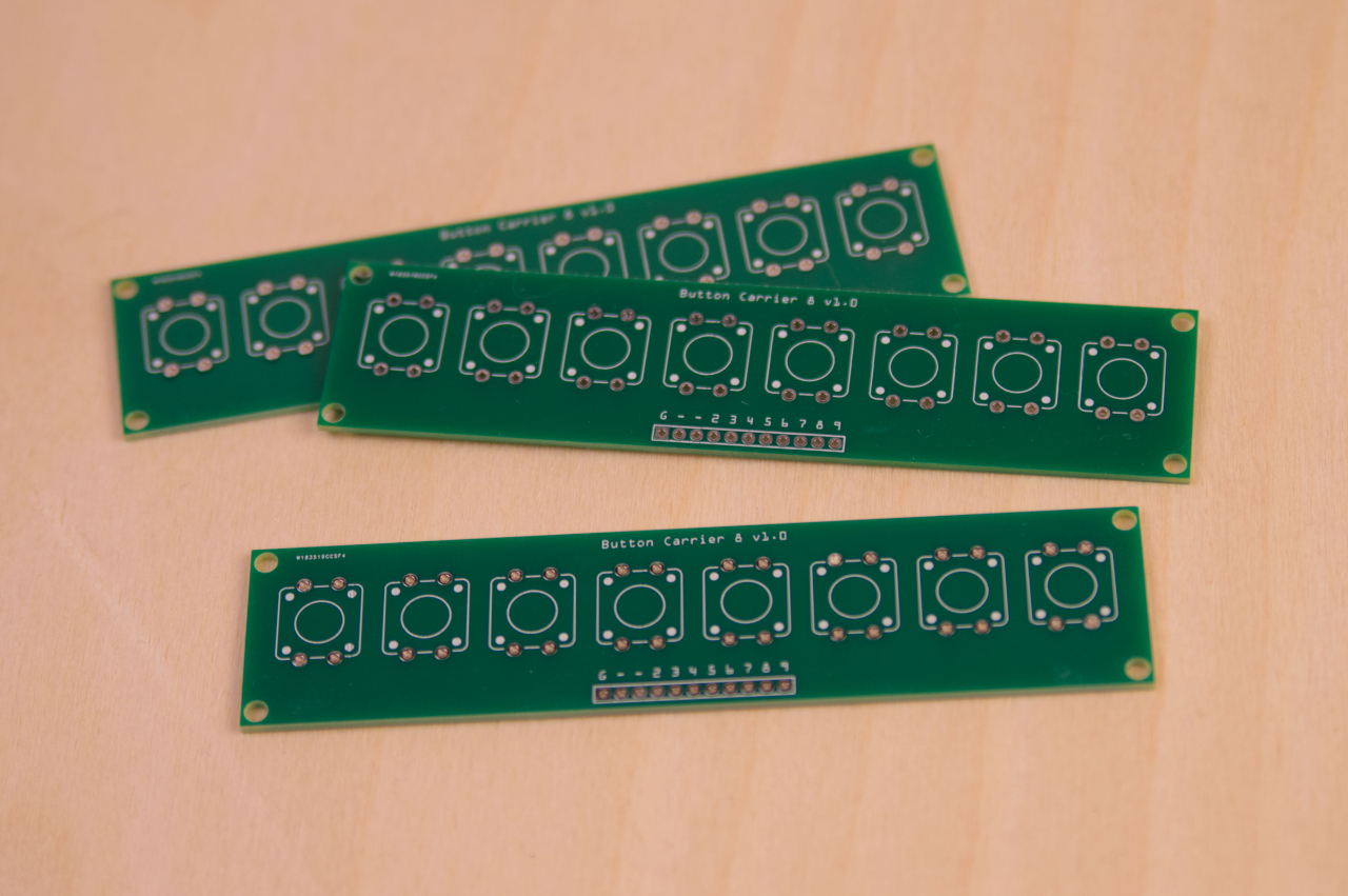
I designed this PCB years ago and I’ve used them a lot in my noisemakers and while I might modify them in the future, they are still pretty useful, so I figured I’d make more.

pcbway-001

I had my Gerber files ZIP’d up and ready for upload, so I started the process with PCBWay, which I assumed would be similar to other PCB manufacturers I’ve used. Yup, pretty close. Note that for color you can choose green, red, yellow, blue, white, black, or “none” at the same cost, but choosing purple, matte green or matte black cost bit more. (Not quite double, but more than just a few bucks.) I’m not sure what “none” looks like, but I am curious.

pcbway-003

So I added the boards to my cart, and I first noticed that I could not change the quantity. This was a little annoying, as I wanted to try different quantities to see how it affected the price. You can do that, but only at the first step in the process, at the “Online Quote” step, not once it’s in your cart, so make sure you know how many you want before your add them to your cart!

When I went to checkout I then found out I could not check out. Right, seems my boards were “Subject to audit.” Yes, they had to be approved by someone (a human I guess) before I could order them, which seemed weird. (Notice the yellow highlighting I added to the cart image above.)

pcbway-002

Now, this is partially my fault, as I didn’t see this the first time I uploaded files. There is a little bit of text on the upload form that shows it could take “10min to 1 hours” for approval. I’m not sure exactly how long it took, as I did this late one night and didn’t get an email about approval until the next day. This was the most annoying part of the ordering process. When I want to order something I don’t want to have to wait hours, or even one hour between putting it in my cart and being able to order it. Perhaps they could make it so that you can place your order, and then if not approved for some reason (?) they could refund the order. Or who knows, maybe this whole “approval” thing is due to some new tariff laws. I have no idea.

pcbway-006

Like I said, pricing is good. I got 75 boards for $32. That’s about 43 cents per PCB. These are tiny boards though, so obviously the price per board goes up when you get larger boards. With approval completed (by some human, I guess) I was able to move on to shipping options.

pcbway-007

I went with shipping via DHL, which came in at $21, so the order total for 75 boards ended up being $53, making each board cost approximately 71 cents. (Obviously ordering more would probably bring that price down, but I really doubt I need more than 75 of these right now.)

I uploaded the PCB files on July 21st, and they were approved and ordered by July 22nd. Manufacturing was completed by July 25th and they were then shipped via DHL July 27th and I got them by July 30th. That’s about an 8 day turnaround for these printed circuit boards. (With some weekend days in there.) Not bad! For US shipping DHL is probably the best option for getting them fast. There were two cheap shipping options, one being an ePacket (which seems to be how I get most of my eBay electronics delivered) which was $8 but had a 10 to 15 day delivery time frame. There was also “China Post” option which was $7 but showed 25 to 40 days for delivery. Wow. So the ePacket is not too bad if you do not need your boards in a hurry.

pcbway-attiny85-pcb-02

The boards from PCBWay look good and got to me fast. They were also very affordable. Overall it was a good experience except for the issue of having to wait until files were approved before ordering and not being able to change quantities once the item is in your cart.

Categories
Uncategorized

Controlling the Controller Cheaply

PCB

Hey, it’s only been six months since my last post about motor controllers and the Power Racing Series so I guess it’s time for an update! If you missed it, I’m working on a tiny electric vehicle that can serve as a reference for teams of beginners to build their own.

Controller

In the last post I talked about a cheap motor controller that required an expensive throttle and alluded to a method of using a cheaper throttle… here is that method.

I started by asking questions on the Power Racing Series Google Group, and people much smarter than myself offered advice, and that’s where I learned about digital potentiometers. I ended up testing my idea with help from this tutorial and eventually got an MCP4131-104E/P-ND digital potentiometer (for less than $1.00) and paired it with an Arduino Nano that was less than $2.50 to create a converter that allows a cheap throttle to be used with a cheap controller.

If at any point you feel like saying “Hey dummy! You should have done it this way!” feel free to leave a comment. Most of my crazy pursuits involve me learning a lot along the way, and this is no exception, so I’ll keep going.

Controller

After I had a working prototype on a protoboard I decided to design a PCB because I’ve been working on getting better at PCB design for the last two years now, and it’s sort of fun (and challenging!) This is the most complex board I’ve worked on so far, and of course, mistake were made…

First of all, see those wires coming off the board? There should be screw terminals there, but I was unaware that the holes were the wrong size and the pins of the screw terminals did not fit. Argh… wires will do for now.

Controller

Everything wired up and ready to go! Except, it didn’t go… Seems I managed to not quite route everything the right way. Back to the drawing, and tracing all the connections with a meter, and I discovered a connection that shouldn’t be there…

Controller

…but that’s what Dremels are for! I was able to cut the trace and get it working. Back to the computer to make a few changes to the PCB. (And yes, I am still using Fritzing. I’ve gotten used to it, and know how it works, so… okay then.)

Controller

A few weeks later I got a new version from our friends at OSH Park and this one fixed the issues and worked! I should still get similar screw terminals but hey, it does what it should do, so that’s something.

You might notice some of the analog pins and some ground connections broken out at the front edge of the board. There are for future enhancements. It would be fairly easy to add in “cruise control” (for parades) or a speed limiter, perhaps with a keyed switch, to allow kids to drive the vehicle safely. (Again, people smarter than me.)

Controller

Whomp! Here’s my “breadboard” showing everything. Batteries to power the motor, and a buck converter to drop the voltage to 12v for the Arduino and a cooling fan. The throttle connected to the converter and then to the motor controller to control things. We’ve also got a DPDT (double-pole, double-throw) switch in there to allow for forward and reverse to the vehicle, and a kill switch, fuse, and voltage meter. Basically all this will need to be jammed into the vehicle to control it. (Don’t worry, we’ll be using larger batteries, thicker wire, and a larger motor.)

Controller

Here’s the controller with a cooling fan mounted to it. I’ll provide files to laser cut or 3D print the mounting pieces, or templates to cut by hand, which is totally doable. (I learned the hard way last year that if not properly cooled the capacitors on these controllers can blow.)

Controller

I also added a bright blue LED to the board (you can choose another color) to indicate when it’s receiving power. Another suggestion I got from someone. I’m sure there is still room for improvement (like, you know, diodes) but hey, it works and I look forward to testing it.

Update! Here is some Arduino code.