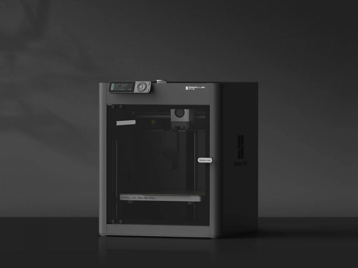
I got a Bambu Lab P1S 3D Printer and wow does it print nice… and fast! We’ll get into that in a bit, but first…
When I got the Prusa MINI back in January 2022 I didn’t really expect to get another printer so soon. I was sort of on a “five year plan”, where approximately every 5 years I would get a new printer (2012, 2017, 2022 if I round the numbers a bit) and I would reap the rewards of the new technology that became the norm over time.
I should note those are just my “own” printers. At my day job (and other places) I’ve used MakerBots, Enders, Monoprice, Flashforge, RepRaps, and Prusa printers. I even gave away two printers without ever really using them because I only have so much space in my shop.
So after getting the Prusa MINI the quality was so good I pretty much stopped using my Monoprice Maker Select Plus unless I had a print that was too large for the MINI. Even then, I would sometimes just split a file and print two parts on the Prusa since it was much more reliable. I even considered (briefly) getting another Prusa MINI but somehow just never did it. I’m glad I didn’t.
I was feeling the itch for larger prints, as the one thing about the MINI that is lacking is… size. It’s print area is 180x180x180 and sometimes you just want a little bit more space. I contemplated a cheap (and large) Ender, but wasn’t impressed by them too much, besides the size and price. Quality is okay, but nothing amazing.

So a few months ago a friend of mine who is even more into 3D printing than I am mentioned the Bambu Lab X1-Carbon he had and told me I should look into Bambu Lab machines… We discussed them a bit, and with the combination of speed, size, and pricing, it was really tempting to get one. My friend then offered me the following: “Get a P1P or P1S and if you don’t like it in a few months I will buy it from you for exactly what you paid for it.” Well, I couldn’t lose. I ordered the P1S a week later.
I had some concerns about The Cloud™ and Bambu Lab being a Chinese company, and not perhaps being a good citizen of open source, and you know what? If I’ve learned anything about my time in this life, it’s that you always have to make compromises. I should also note that the Bambu Lab P1S (and the Prusa MINI) are primarily used for my business, so things like cost and quality come into play there. If I can produce high quality parts in less time, that’s good, and sometimes I have to choose what is good for my own business and my clients. (Or at least be willing to compromise a bit on things.)
Now, I am a huge fan of open source, and I contribute to projects like OpenSCAD and Inkscape which I use in my work, because I want to see them continue. I like the fact that I could probably rip apart my Prusa and rebuild it and feel like I’m in control of the hardware. With the Bambu Lab machine, it feels a bit more proprietary and difficult to repair or replace parts. An acquaintance suggested to me that “Bambu Lab represents everything you’re against!” and sadly, I take part in things every day that I’m against, but that’s living in the modern world. I try to make choices that cause less harm, but it’s not always easy.

Okay, have I justified the printer yet? Let’s hope so… Moving on to the actual device, the Bambu Lab P1S is pretty damn amazing. It prints about three times the speed of previous printers I’ve owned, and the quality is off the freaking charts. I’ve seriously never seen prints look this good from a “consumer” grade printer. They say “Works right out of the box, set up in 15 minutes” and that is pretty accurate.
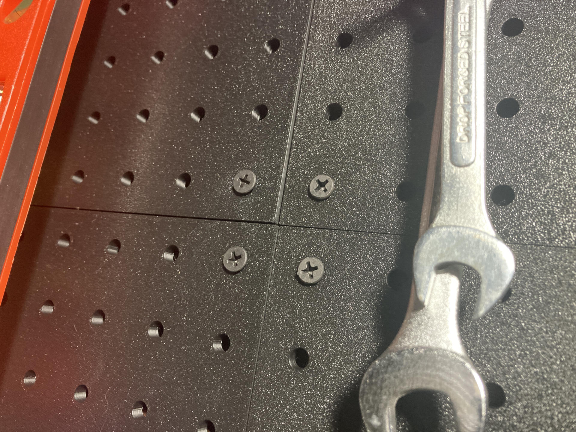
You can avoid the cloud stuff if you want. You can use LAN mode, you can FTP files to the machine’s SD card, or you can sneakernet the SD card if you want. You can also use OrcaSlicer if you don’t like the Bambu Studio software. You also definitely do not have to use Bambu Lab filament. Buying replacement parts is probably best done through Bambu Lab (for now) but there are some third party items already… I got a third party build plate that works just fine.
I know with more proprietary devices you’re somewhat at the whim of the manufacturer, and can see it two ways. If things go south you (and every other owner) can attempt to hack the crap out of it, load new firmware, replace components/brains, etc… or replace it. Machines are getting cheaper all the time, and let’s be honest, most people don’t keep things around as long as we used to. (I mean, it’s sad but true.)
I should note I do not have the Bambu Lab AMS unit, which allows for multi-color and multi-material printing. I really don’t see the need for the things I produce, and the multi-color printing is extremely wasteful (in materials and time). For now I’ll stick to single color/material printing.
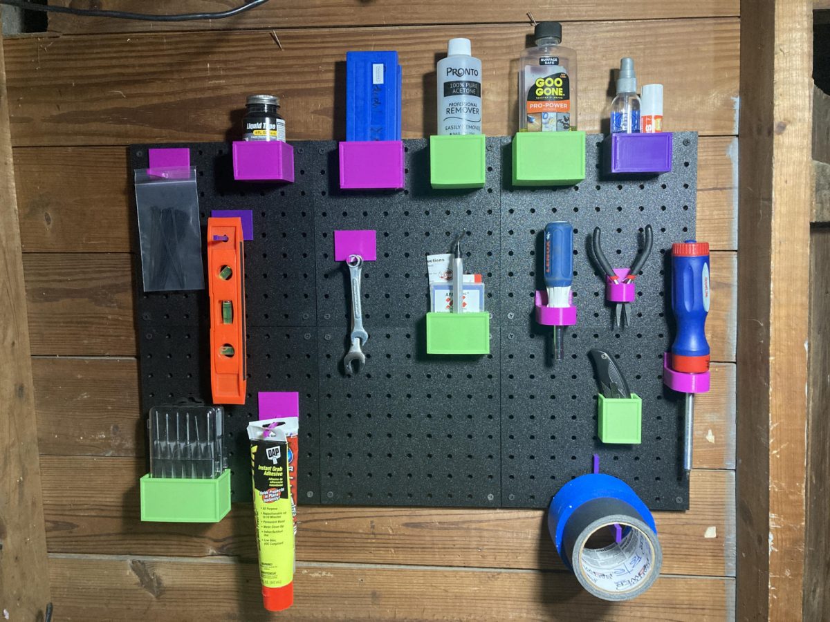
Let’s look at a few more prints…

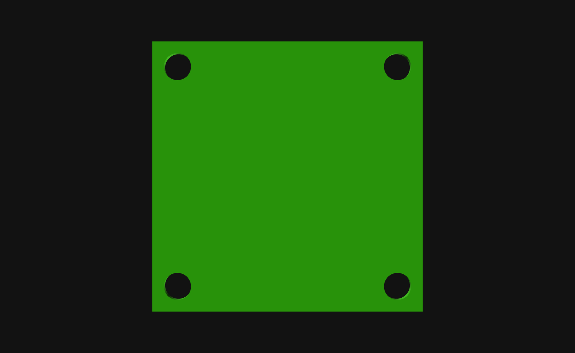
Here’s a tray I printed to fit perfectly under my monitor stand. It’s 180x180x45, which is larger than I can print on the Prusa MINI. I ran out of filament when printing it so had to load a second spool, which worked just fine (as expected) and looks pretty good since it’s a two-tone green now.
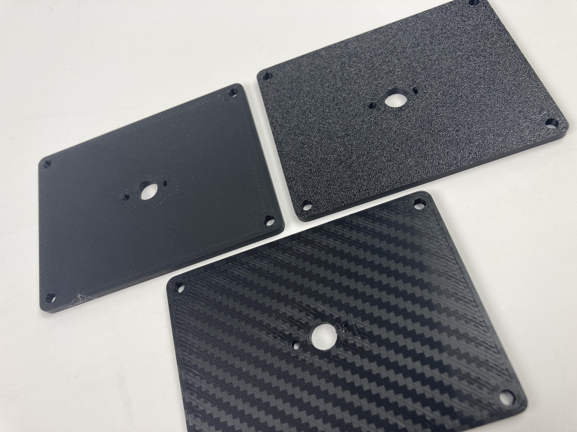
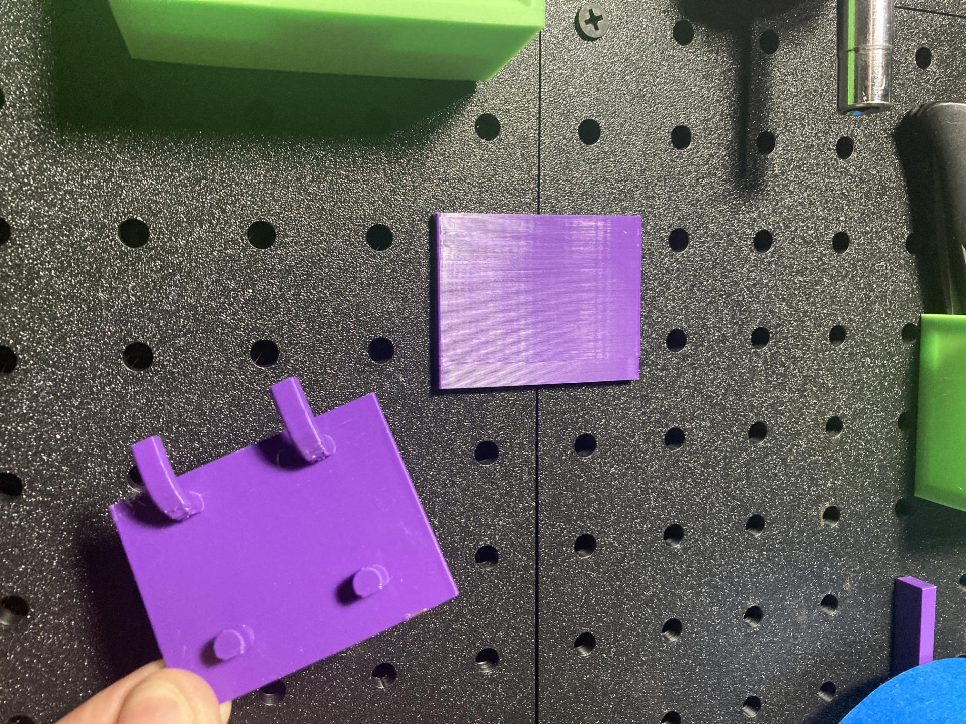
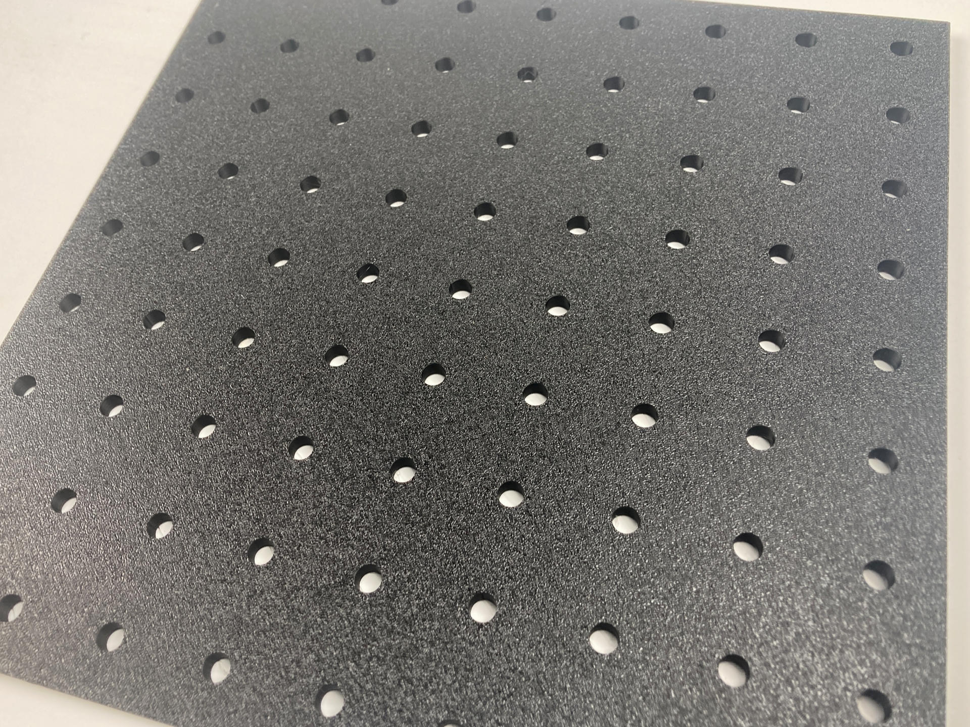
I was always amazed at how smooth (and perfectly printed) the bottoms were on prints from the Prusa MINI, and the P1S does a good job as well, but damn… that textured bottom is beautiful. It just hides any imperfections and gives a “hey, this is not 3D printed” look to things. The “fake carbon fiber” look is from a cheap PET build plate I got from Amazon and it’s a nice option as well. (These were all early prints and I’ve improved the quality a bit since then.)
But wait, there’s got to be something(s) wrong with this printer, right? Of course!
Control Panel (and Screen)
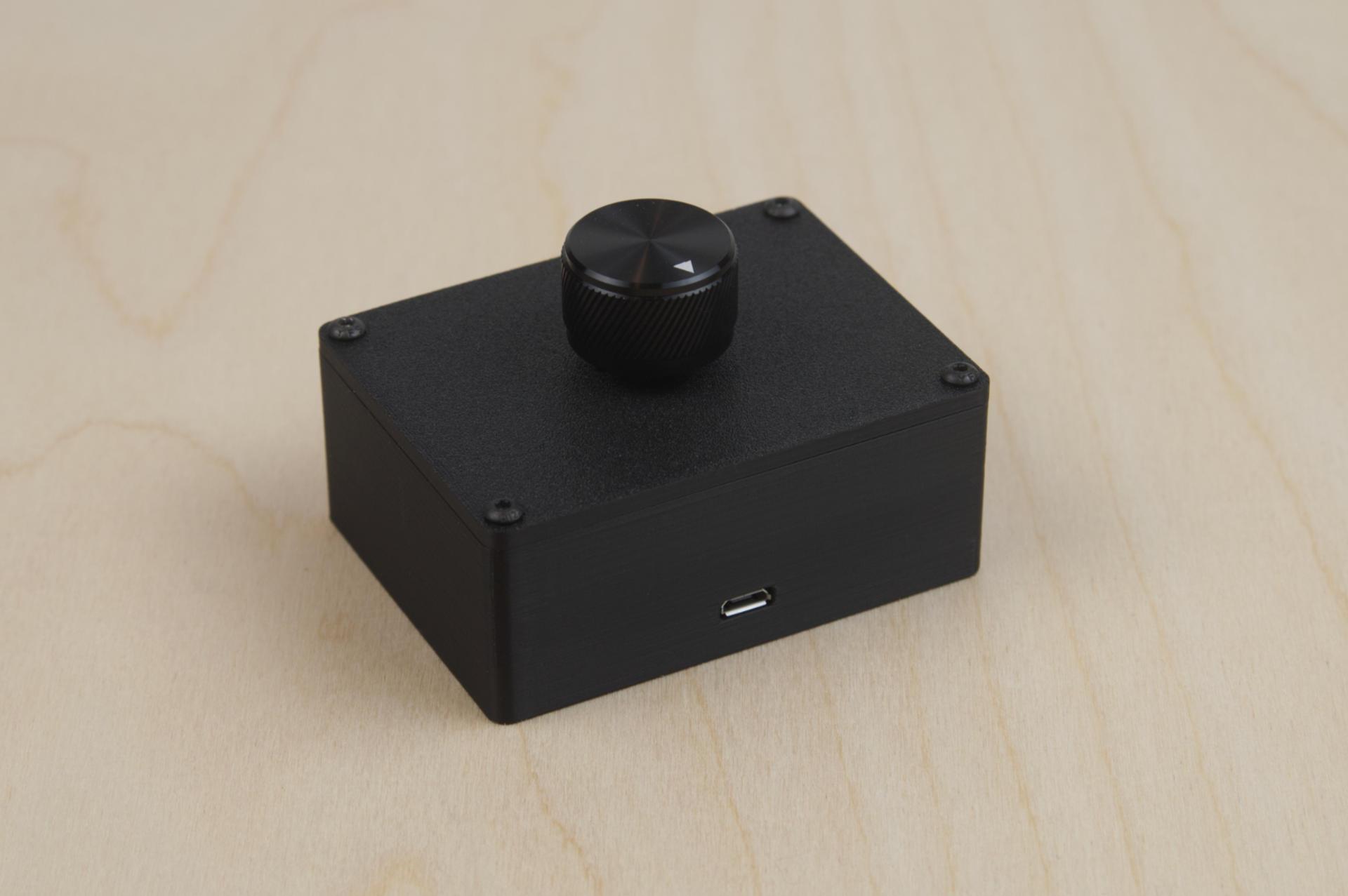
The control panel & screen leave a bit to be desired. It’s been describe at a “90’s car stereo” and it’s barely a step up from the two line LCD displays that were popular on printers a decade ago. It’s usable, and I don’t totally hate it, but it does sort of suck. The X1-Carbon has a huge-ass screen! But hey, that’s how you differentiate products and justify pricing, right? Still, even the Ender-3 S1 has a better screen. I absolutely love the interface on my Prusa MINI, which is a nice screen with a click wheel. My old Monoprice MSP had touchscreen. So yeah, screens are a weird thing. (I’m considering adding a DIY xtouch controller.)
File Storage & Workflow
The P1S uses a Micro SD card. Yeah, those tiny ass little cards you could easily swallow. I much prefer a USB port I can stick a USB thumb drive into. Also, there is no support for folders, so managing files on the SD card is nightmare of one long list of all the files. There is a single folder called “cache” that holds any file that has been previously sent from the Bambu Studio software. I would love to see folders. I use the folder feature all the time on my Prusa MINI. (One more great feature of the Prusa MINI is that when you plug in a thumb drive it queues up the most recent file added to the drive and pops it up on the screen and you can print it with one click. This is the right way to do it.)
That said, most of the time I end up using Bambu Studio (the slicing software) to send files to the P1S. This is the first printer I’ve had with built-in WiFi. I do like the convenience, especially since the lack of folders makes it nearly impossible to manage files on the device. (I should probably just make a separate Micro SD card for production, with all of my regular files on it, and swap it in as needed.) I am, of course, not a huge fan of The Cloud™ and you can opt not to use the cloud, but you lose the ability to monitor prints remotely.
Slicing & Sending Files
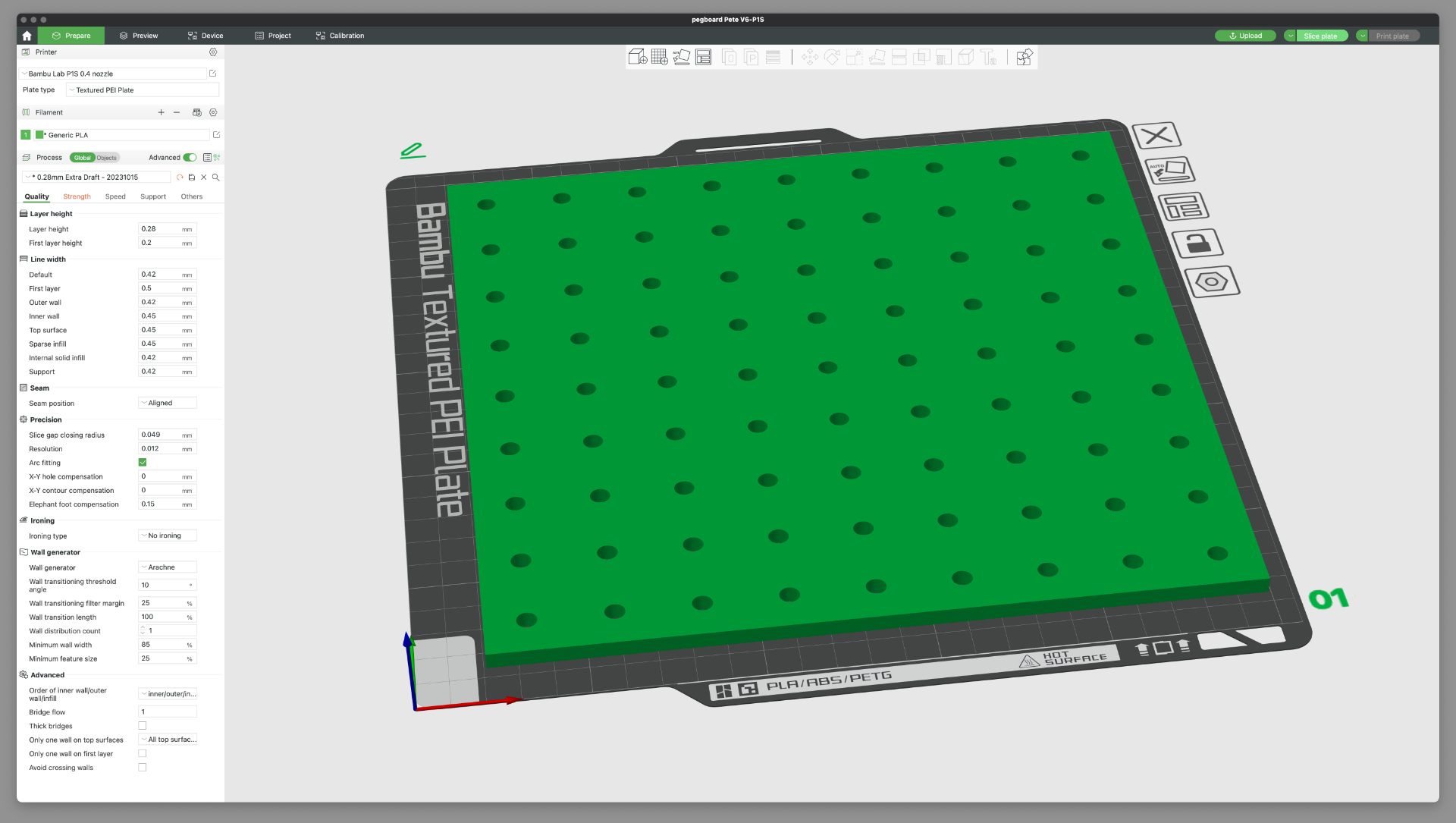
Bambu Studio has a few weird quirks, but there’s always OrcaSlicer. Bambu Studio was forked from Prusa Slicer, so under the hood much is the same. (You can also do a few things in config files where there is no interface to do them in Bambu Studio.) So typically I slice a file in Bambu Studio and click “Print” then send the file. The file actually goes to the cloud and then to the printer. Now, there is a “LAN only” mode to avoid the cloud, and you can actually FTP files to the SD card as well, but you can’t start them from Bambu Studio. You can also just “Send” the file from your computer to the SD card, so you can hit “Print” on the machine, but every now and then this does just not work for me.
Beep Beep!
Believe it or not, the P1S lacks a piezo speaker. It cannot beep at you. M300 commands in G-code are ignored. I find this omission sort of ridiculous.
Conclusion
Overall it’s a weird mish-mash. If you just do the cloud thing that is the easiest, but for no-cloud you can put files on the SD card (but not in folders) and print from the machine but not from Bambu Studio. I didn’t even mention Bambu Handy, the mobile app for monitoring and controlling the P1S. (I may need a second post!)
Okay, that’s it. I’m gonna end this post by saying the Bambu Lab P1S is a printer that costs $700 USD, prints high quality prints, really fast, and has a lot of nice features. Does it lack a few nice features, yes it does, but again, at that price (for a 256x256x256 build volume) I can live without a few niceties. If you want those niceties and have the budget, go for the Bambu Lab X1-Carbon instead.