Categories
Uncategorized

#TeamArduinoCC

Arduino.cc

In accordance with a request from organizations and people I respect, here’s a photo take on 2015-04-19 showing the packaging from an Arduino UNO I purchased from Adafruit Industries (in the United States of America) on 2010-10-19 showing the text “Manufactured under license from Arduino by SMART PROJECTS S.r.l.”.

Adafruit / Arduino.cc

Here is the order information from that purchase. For more info, see the Hackaday post Your Arduino Packaging Could Sway a Court Case and the Adafruit post Please post old Arduino packaging that says “Manufactured under license from Arduino” #TeamArduinoCC.

Categories
Uncategorized

More Rotary Encoding

When last we discussed rotary encoding, it was all experimental. Since the project (which will eventually be revealed) is complete, I figured I should share a bit more about the exploration and final solution.

Encoding Disk

I moved from printed paper disks to laser-cut disks. I cut some 3mm Baltic Birch plywood at Milwaukee Makerspace. They worked well, but since I was hoping to get more steps/resolution I continued with the paper prototypes as well.

Encoding Disk

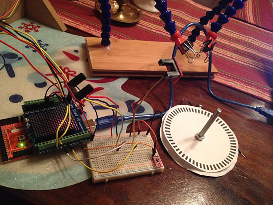
The one in the photo above was a bit too fine… too many steps. The more steps the more precise the alignment has to be, and the more chance of errors.

Gap

We had some concerns about a disk spinning between a U-shaped sensor with just a few millimeters on each side, so rather than just go with the GP1A57HRJ00F Photo Interrupter, I started experimenting with the QRD1114 Optical Detector / Phototransistor as an alternative.

Sensors

The idea would be to use a wider disk and instead of it spinning between two pieces, it would have the encoding stripe on the edge, and the sensors would be on the outside of the disk. Back to the breadboard! The QRD1114s require a pair of resistors to work properly, so I wired it up and did a few tests and things seemed to work.

Encoding Strips

My first tests just involved sliding a piece of striped paper across the sensors, but I needed a real disk. I used the laser cutter at Brown Dog Gadgets to cut some disks from 1″ pink foam, and also from 1/4″ foamcore board. The pink foam actually ended up with concave sides due to the melting power of the laser, so I used the foamcore board pieces stacked up.

Stripes

Math time! How long of a strip do we need to wrap around the disk? Well, you can determine the circumference of a circle if you know the radius or diameter. Hooray for math! Above is a letter size file that I could print on a laser printer to produce the stripes I needed. The thin line on the right side was used for alignment since I had to use multiple stripes to wrap around the disk.

Encoder

Here’s a sneak peek of what the final disk looks like. There’s a few more steps before we got this far though, so I’ll continue the story next time.

Categories
Uncategorized

Polargraph Experiment #1

Motor Mounts

I needed a few motor mounts for a project and since I was at Milwaukee Makerspace it seemed quicker/faster to just laser cut a few since I had files on my laptop. (I could have 3D printed them as well.)

Polargraph

I assembled a quick and dirty polargraph, and while I attempted to use an Adafruit Motor Shield I had on hand, it did not work. The steppers were not moving, just humming and stuttering.

I then grabbed the CNC Shield I’ve been testing and put that in place. The steppers worked fine with a test sketch, but the firmware I wanted to load (Dan’s Makelangelo code) expects either an Adafruit Motor Shield or a RUMBA board. I thought about trying to rewrite things to work with the Pololu motor drivers, but it was also after 11pm.

(I later realized that I should have looked at the RUMBA firmware, as that supposedly works with RAMPS. And yes, while I do have a spare RAMPS board, it’s across town at my studio. I decided to punt and see what I could do with what was in my workshop.)

Shapes

I figured I’d throw Grbl on it and see what happened. I used Grbl Controller to connect to the board and loaded some G-code to run. I knew it would not work (as expected) but I tried anyway.

Drawing

Grbl supports machines that use Cartesian coordinates, but not those that use polar coordinates, like a polargraph. Still, I was surprised at what I got. It basically worked, except for flipping the image and running it diagonally up to the left.

Grbl Controller

I then took my original vector file and flipped it, and skewed it up and to the left, to match (somewhat) how it was drawn by the machine.

Shapes skewed

It actually sort of worked! I think it was after midnight by now so I gave up on it. My lack of math skills prevent me from converting between coordinate systems, but I think there’s a few things to explore here, and if I get time (uhhh) it may be something I play with a bit in the future. Also, if anyone wants to add polar coordinate support to Grbl that would be lovely. :)

Categories
Uncategorized

Rotary Encoding

Rotary Encoding

For an upcoming project we want to use rotary encoding with optical sensors, so I did a bit of hacking testing today…

I’m using two photo interrupters mounted on breakout boards with 220 ohm resistors.

For an encoding disk I searched for a suitable SVG file and found this blog post, which just happened to have a link to a perl script (of course!) to generate encoding disks. A little Inkscape magic and I printed out a disk to test with.

I should note that my original plan was to use the Silhouette Cameo to cut the slots in the disk, but the paper version actually worked fine for testing. In the final piece we’ll probably use a piece of laser-cut acrylic.

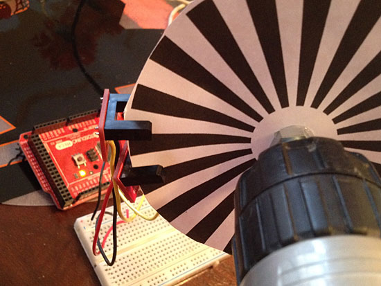
With my encoding disk ready I hot glued it to a bolt and chucked it in the drill. This gave me an easy way to vary the speed and direction.

Rotary Encoding

I grabbed the Encoder_Polling library and used the counter example and that was about it. I could now see if the disk was spinning and in which direction (by looking at the numbers increase or decrease.)

I really thought I’d need to mount the photo interrupters more precisely, but I pretty much left them hanging in mid-air supported by wires on a breadboard and it worked fine. (Maybe I just got lucky?) There’s a lot more code to write, but this was a good start.

Oh, if you want to learn way too much about reading rotary encoders with an Arduino, visit the Reading Rotary Encoders page and set aside a few hours…

Note: I also found an online encoder wheel generator.

Categories
Uncategorized

Arduino(ish) Keyboarding

Teensy 2.0
Teensy is teensy

For the past few years I’ve been building devices that can emulate computer keyboards. Typically I’ve used the Teensy microcontrollers for this along with the Arduino IDE and the Teensyduino add-on. The things you can do with a Teensy to emulate a keyboard are very impressive! Basically, it’s the best way I know of to create your own custom USB keyboard.

Comparison
Size matters – A-Star with Arduino Micro and Leonardo

When the Arduino Leonardo was introduced, one of the features I was interested in was the ability to emulate a USB keyboard. I never actually got a Leonardo to test this with, mainly because the form factor was too large for my projects. Sometimes shield compatibility is good, sometimes the smallest board wins.

A-Star
Size matters!

I recently got a Pololu A-Star 32U4 Micro, which is a tiny (and cheap, under $13USD) board very similar to a Leonardo, once again using the Atmel ATmega32U4.

There may be a little bit of work involved in getting the A-Star up and running. There are drivers needed if using Windows, and (supposedly) a little more work to get things going with Linux. I had no issues with Mac OS X, but I’m pretty familiar with add-ons for the Arduino IDE due to using Teensyduino. You can also just pretend this is an Arduino Leonardo and that seems to work fine.

(I also can’t tell if the Pololu A-Star 32U4 Micro is open source hardware. They do have a bunch of files available, but I did not see an explicit “Open Hardware” note anywhere. It’s worth mentioning that the Teensy is not open source hardware. If that’s not a big deal to you, then it’s not a big deal to you. The official Arduino hardware is of course, open source.)

I’ll probably keep experimenting with the Pololu A-Star as a keyboard emulator for simple things, and stick with the Teensy for more complex things. I’ve also heard that the Teensy 2.0 will disappear in the future, which isn’t a huge deal, as the Teensy 3.1 is a big improvement over it, but the 3.1 does cost a bit more than the 2.0, so that’s one factor to consider when evaluating which board to use.

Have fun building your own keyboard!

Update #1: I’ve been talking to Pololu and they suggested the A-Star may actually be able to use the Teensyduino Keyboard libraries. I’m awaiting more info on this, as it would be an exciting development.

Update #2: It looks like the Teensyduino Keyboard libraries cannot be installed onto the A-Star, which is good to know. But don’t worry, I’ll be using the A-Star for some future projects anyway. ;)