The latest fun project over at Brown Dog Gadgets is a USB device to toggle your microphone and camera on and off during video calls on your computer. Check out Meeting Controls!
We’ve got the “Business Edition” above for the adults with their serious work calls, as well as the “Fun Edition” for kids stuck in those all-day distance learning sessions.
This is a pretty simple build if you’ve got the right LEGO pieces laying around. (If you don’t a quick trip to BrickOwl.com will get you sorted straightaway.)
As always, you don’t have to perfectly replicate the LEGO build we’ve done, and it should be considered a starting point, or recommendation of one way to do it. That’s the beauty of LEGO building… it’s open ended. (Of course we do have a few tricks along the way.)
The Invention Board can be programming to work as a USB HID device, and we provide all the code you’ll need to work with Zoom, Google Meet, and even Microsoft Teams. (Webex didn’t work… blame their developers.)
Some nice touches, like the mic and camera icon, were added by using a vinyl cutter to make small stickers that are applied to flat LEGO bricks. Totally optional, but adds a bit of class and distinction to this very handy device.
As always, a wiring taping diagram and notes on the build are included in an eye-pleasing arrangement of words and images. Check out this project and more from Brown Dog Gadgets, especially if you’re an educator looking for a great invention & creativity platform that combines circuits with LEGO building.
I remember seeing people use a Game Boy Camera years ago, and with my interest in lo-fi tech (and probably spurred on by 8bitMKE) I ordered a Game Boy Camera for $11.97 on eBay almost two years ago (Hey, sometimes projects take a while.)
Last fall when my daughter moved out we found her old Game Boy Advance, and after a good five minutes of Tetris I popped the camera into it and took a few photos. But alas, with no way to transfer them out of the Game Boy, they were stuck there…
After some digging around I found some posts that mentioned using an Arduino to transfer the photos from the Game Boy to a computer. Arduino you say? That’s my jam! But even then it took some time before I did anything.
I finally got the cable I needed (a “Two Player Link Cable Cord for Nintendo Game Boy”) for $3.99 on eBay after first ordering the wrong cable, and I quickly grabbed an Arduino Nano, one of my breakout boards that was already soldered up, cut the cable in half, stripped the wires, grabbed a multimeter to figure out which was which, and got it all wired up.
The process to transfer involves connecting the Game Boy and “printing” the photo you want while the Arduino serial monitor is open and set 115200 baud. The data will flow into the serial monitor window, then you copy it and paste it into the decoder and you get your image.
While I’ve got a DSLR, a phone, a Raspberry Pi camera, and other ways to capture images, the Game Boy Camera is definitely one of the more esoteric methods of doing so. Stay tuned to see what I actually do with it.
I finally got around to publishing the files for the Beginner Arduino Class I used to teach.
Here’s some text from the README:
In 2016 I taught a classed titled Electronics & Sculpture in the Peck School of the Arts at the University of Wisconsin Milwaukee. I often referred to the class as “Arduino for Artists”.
Basically, it was teaching art students, some of whom never programmed or wrote any code, how to activate their art using the Arduino platform.
We had five concepts we wanted to cover:
Digital Input
Digital Output
Analog Input
Analog Output (PWM)
Serial Communications
In 2017 I moved on to teaching the class at Milwaukee Makerspace and I refined the curriculum a bit to resemble very closely what you’ll see in these files. I used components I had available. (Note: I should add a parts list at some point).
In 2018 I started teaching the class at Brinn Labs, usually with the help of Becky Yoshikane (friend, former coworker, former student, and former classmate). We taught the class all through 2018 and a few times in 2019.
I no longer teach the Beginner Arduino Class, but I wanted to share the files in case anyone else could find them useful.
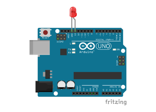
Each lesson contains an Arduino sketch and a wiring diagram (as a Fritzing file, and a PNG file). In some cases there are also images showing components, and most of the sketches should have links to the concepts/functions used in the sketch.
So there you go. If you find any of this useful, let me know. I wish I was in a position to keep teaching the class, as I really enjoyed doing so, but it’s not something I can do right now, but maybe you can. Let’s keep trying to teach electronics and prototyping to people and see what happens!
The folks over at Seeed Studio sent me a Seeeduino Nano to check out. I’ve used a lot of Arduino boards over the years, including plenty of cheap Arduino Nano clones. Most of the clones have worked fine but every now and then I’ve seen a bad one come through. The Seeeduino Nano is a nice quality board with a little extra to make it useful for beginners or people more interested in making things quickly/easily than they are soldering wires.
One interesting thing about the Seeeduino Nano is that it used USB-C to connect to your computer. While most of the Arduino UNO boards I’ve used still use USB type B, and lots of other boards use Mini-USB or Micro-USB, the Seeeduino required a USB-C cable. Luckily, I had one on hand. If you don’t already have a USB-C cable, you’ll need one for the Seeeduino Nano.
My favorite part about the packaging of the Seeeduino Nano is the warning on the back that says “Best to keep away from fire”, mainly because I’ve worked on multiple Arduino projects that specifically involved fire… But I digress… for most people keeping away from fire is probably a good idea.
Here’s the top view of the Seeeduino Nano next to a ELEGOO Nano board. You can see the difference in the USB connector and a few other features. One difference with the ELEGOO boards is that they come with the header pins included but not soldered in place. (Here I’ve soldered them to the board.) There are times when you don’t want header pins solder into place. My guess is that for the target market of the Seeeduino Nano, the pins already installed makes sense.
Another thing about the ELEGOO boards is that I can’t easily find them listed on the web site. Here’s a post about them, but in the past if I’ve purchased them I’ve found them on Amazon for a price close to the Seeeduino Nano, though I’ve only seen them as a 3-pack.
(Note in the photo above the boards are the same dimensions, the Seeeduino is just on an angle due to the extra connectors on the top.)
Since I had a project already done with a Nano in place (via my Anrduino Nano Breakout Board) I just swapped in the Seeeduino Nano, uploaded the code, and it worked great.
Where the Seeeduino Nano really shines is the capabilities it has with the Grove system from Seeed Studios. If you don’t want to solder, and also don’t want to stick a lot of wires and components into breadboards, the Grove system might be what you are looking for. Again, I see this is a match for those who are more interested in the code than the wiring of electronics, or for workshops where soldering might be a concern (with kids or those not able to solder for other reasons).
Above you’ll see the Seeeduino Nano plugged into the Grove Shield which has a Temperature & Humidity sensor attached. This takes seconds to connect versus soldering things or plugging things into a breadboard. When I taught basic Arduino classes I always told students to unplug their Arduino when they wired up the breadboard, and then to double-check the wiring for errors before plugging in the board again. The Grove plug-in system eliminates much of that guesswork. You can’t really plug things in backwards.
I grabbed the example code Seeed Studio provided and had a few issues. Nothing I couldn’t fix, and I did open an issue about it. In the end I grabbed Adafruit’s library for the DHT Sensor as well as the Adafruit Sensor library (which is required by the DHT library) and got things up and running. If you’re not interested in downloading zip files from Github you can also install these libraries right from the Arduino IDE.
Overall the Seeeduino Nano is a good quality Arduino board, and the Grove system makes it very easy to get up and running. In this specific test I did run into some trouble with their example code, but in most cases those issues are solvable, and there’s probably an alternative example or library out there that will do what you want or need.
Finally, here’s a short video of the game scoring system I mentioned above. The Seeeduino Nano is taking input from a number of pins (that will eventually be triggered by switches or buttons) to keep score, where each pin is a different point value, and then using the piezo speaker to play a sound for each point value as well as displaying the points on a small LED display.
Launching a ship is exciting! Maybe that ship is a rocket ship, or maybe it’s a traditional ship which floats in the water. When launching a ship there’s often a ceremony involving some champagne and pageantry and a party and it’s quite an event. (I’ve been to at least one boat launch, so I know what I’m talking about!)
When you launch a new version of your software, it’s not quite as exciting. I mean, it is, but in a different way. Sure, twenty years ago there was probably a lot of excitement around master discs and packaging and all that, but in 2019 with most software delivered as a service, it’s not much more than someone typing a few commands, clicking a mouse, and pressing the enter key. Not as exciting.
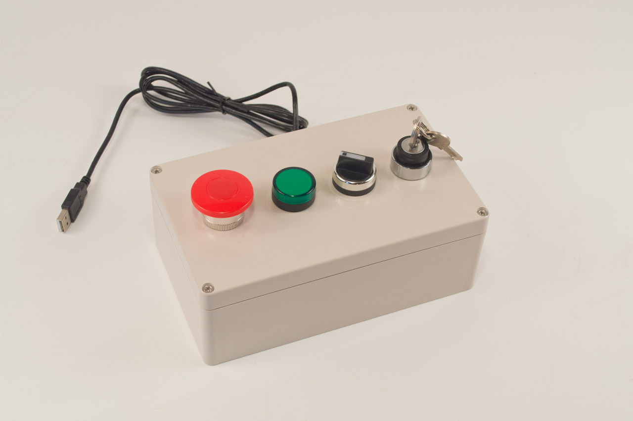
But! Some software company decided to make it exciting, and they asked me to help. They’ve now got a “Software Release Device” that they can connect to a computer, then turn the key to enable the device (which turns on a lamp letting them know it’s ready) and then they can switch between mouse and keyboard and hit the big read button to launch the latest version of their software to the world. Exciting!
They made it pretty easy for me, as they specified most of the parts for the build. The lamp was meant to run on 24VDC but luckily it was just a matter of cutting open the housing, replacing some resistors, and gluing it all back together to get it to run on 3.3VDC, and it looks really nice.
If you’re interested in some sort of custom USB device, let me know… I’d love to build something for you.