Categories
Uncategorized

Single Stroke Font

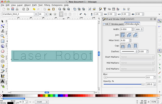
I needed a single stroke font for some laser cutting. You’d think that would be an easy thing… Well, keep reading.

When laser etching, any font could be used. You can raster etch the type, or “vector etch” the type. Raster etching takes a long time, and vector etching (basically doing a low-power vector “cut”) is fast. If you’re doing 3,000 pieces, the time can make a huge difference!

Regular font

Here’s a normal font in Inkscape. Fonts consist of an outline which is then filled with a color. In this case, the outline of the font is filled with black and you see what you normally see when viewing a font on a computer screen.

Regular font

Here’s the normal font with the fill set to none and the stroke (outline) set to a thin line. You could laser etch this (and some people do) but you’re now outlining the letters instead of just etching them with a single stroke. This is fine, but takes more time. Since going really fast is our goal, this doesn’t work.

At this point, you may be thinking “No problem! Our pals at Evil Mad Scientist Laboratories have us covered with Hershey text, and engraving font!” Indeed, Hershey text is awesome, but not always the right solution. I use Hershey text often, and it’s lovely, but let’s keep exploring…

CamBam font

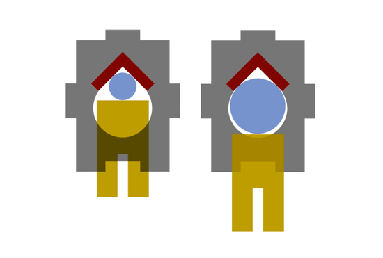
I found these CamBam fonts, which probably work quite well for a spinning bit that is cutting material, but there’s an issue:

All the fonts are built using a 100% overlap in the font design, which tricks my TrueType font design program into thinking they are really looped TrueType fonts, when they really don’t have an inside and outside loop.

CamBam font

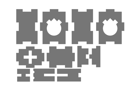
A spinning bit cutting material is quite different than a laser cutting material. If you use this font to laser etch, it will double up, which mean you’re lasering the same thing twice. This takes longer, and cuts your material twice. No good.

You can manually go in and delete the overlaps, but it’s a time-consuming pain, and you’ve got better things to do.

Machine Gothic

I found Machine Tool Gothic, which looks a bit weird when you first select it, but we’ll fix that. Remember that fonts are typically outlines that are filled with a color. That’s what is happening here.

Fixing Machine Gothic

We just need to set the fill to none, and give it a thin stroke. Much better! We’ve nearly got our clean single-stroke engraving font.

Fixing Machine Gothic

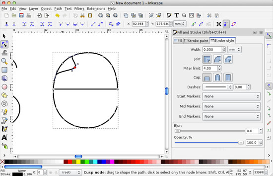
Let’s fix the weird lines that connect everything and close the paths. First you’ll want to convert the type to outlines (that’s the “Object to Path” command in Inkscape) and then select the two nodes at each end of the line you want to delete and use the “Delete segment between two non-endpoint nodes” feature to remove the line.

Fixing Machine Gothic

Oh, it’s worth noting that when you convert the type to paths, you lose the ability to edit it as type. More on that later. Here’s the “L” with no extra line connecting everything.

Now, it may look like only certain letters need the extra line deleted, but they all do. Go through each letter to delete the extra lines! If you’re doing a one-off project this may not matter as much, but if we are laser cutting 3,000 pieces, even an extra 5 or 10 seconds per piece will make a huge difference.

Type on a curve

Here’s the real reason I wanted to use an editable typeface rather than the Hershey text extension. With text, you can place it on a path. This means you can curve the text onto a circle or some other shape. We want to make sure we’ve got the text exactly as we want it before removing the extra lines. (Remember that we need to change the editable type into outlines before we remove those extra lines.)

Type on a curve

Don’t forget to remove the circle, or whatever path you used to place your text on.

Type on a curve

Fire up the laser! Here’s our clean and ready to vector-etch single-stroke type.

Categories
Uncategorized

FND Improvements v3.75

FND v3.75

A few weeks ago I designed what I like to call “version 3.5” of my main drawbot platform. The improvements were still mainly a two dimensional design, with horizontal plates sandwiching things together. I found two main faults with this design, so I started working on improvements.

The first improvement was in the tool holder. The one with rubber bands proved to not be strong enough to hold tools in place easily. The rubber bands were a pain to work with. (They did work well enough to hold clay carving tools though, and we ran the drawbot across some slabs of clay.)

I wanted to move to a new design where a screw could be used to hold the tool. I know that the Egg-Bot uses a screw, and for the unfamiliar, it looks like this.

Egg-Bot Pen Holder

This is a great design, but for various reasons I chose not to attempt to copy it. Instead I borrowed some ideas…

FND Pen Holder

The screw I’m using is a standard 8-32 screw with a wing-nut threaded on backwards to the head, and then a hex nut is added and tightened against the wing-nut. On the other end is another square nut to push against the tool, and again there’s a hex nut tightened against it.

In the above image showing the parts for the tool holder you’ll see the first and third pieces have holes for the screw to go through, while the second plate has a square hole to hold the square nut between them. So far it’s working quite well, and holds things without any slipping or wobbling.

Most of the rest of the plate is similar to the previous version, with the exception that now there is no bottom plate, as this mounts directly to the body.

The previous version relied on four screws and eight hex nuts to hold the motors between two plates. This was less than ideal for a number of reasons. First, there was no good way to align the motors and tighten things up. Alignment isn’t a crucial element of the drawbot, but it’s nice to have. The second issue was structural, as the 3mm wood was flexing quite a bit. I didn’t even try acrylic, but it probably would have been worse.

FND Servo Mount

The new version of the motor mount is much improved! I’m sure I’ll have an issue with some of the other servos I’m using, as they aren’t all the same size, but it should be as simple as printing two new parts with the properly sized and spaced holes. Again, there’s only three parts because this mounts to… the body!

FND Body

Here’s the new body platform. It’s got all sorts of mounting slots and such. The tool holder gets assembled and then attached to the body. (The “assembly” involves a lot of wood glue at this point.) The motor mounts are glued into place on the body as well. It’s nice finally having things rigid and not held together with hot glue and rubber bands. (Well, some things.)

At this point I’ve basically got a (semi-) generic platform with no specifics on electronics or components. You can fit any number of controllers and battery packs on it. That will probably change in the future as I choose the parts I plan to use.

FND 3.75 Plate

The whole plate fits in a 280mm x 100mm area. That’s just under 12″ x 4″, which means you could fit three of them on a 12″ x 12″ sheet of Baltic Birch.

On to the next revision!

Categories
Uncategorized

Mixing Imperial and Metric

Converting Imperial to Metric

In an ideal world, we’d all be using the Metric system, but the world is far from ideal, and math is confusing, so we’re sort of stuck.

Most of the design work I do for objects (laser cut or 3D printed things) is done in millimeters. This makes sense, and is oh so easy compared to trying to use those damn inches! Sadly, I grew up with Imperial Units, and while I can roughly estimate what 12 inches is, I still have problems visualizing something like 100 millimeters. I can usually remember that it’s about 4 inches, but it’s still difficult to put my hands in space 100 millimeters apart without first converting it in my mind to 4 inches.. Dammit!

Converting Imperial to Metric

So I end up converting values. Typically using Google’s conversion utility (because I’m in front of a computer 98% of the time I’m designing something.)

So if I wanted to find the Metric equivalent of 69/500″ (also known as 0.1380″) which is the diameter of a 6-32 bolt, I can find out. Oddly enough, when it comes to the small numbers, visualizing things is the opposite! It’s easy to visualize 3.5mm but impossible for me to imagine what 69/500″ looks like. Whatever!

Here’s a simple chart of bolt sizes I’m posting just for my own use.

5-40 0.1250″ 1/8″ 3.175mm
6-32 0.1380″ 69/500″ 3.5052mm
8-32 0.1640 41/250″ 4.1656mm

Update: A larger chart!

While I would love to use Metric hardware more often, it’s expensive! I usually just buy random bits from the local hardware stores, and the Metric stuff is in short supply, and cost more. I find it quite annoying. I don’t know if prices online are any better, a quick search seemed to suggest not.

(And don’t even get me started on pixels!)

Categories
Uncategorized

Drawbot Tool Holder

One of the issues I’ve had with the Friday Night Drawbot is the part that holds the tool has never been very solid. In early revisions I used corrugated plastic, and would just use an X-ACTO knife to cut a hole for a Sharpie, and it would work well enough, and when the plastic wore out, I’d replace it with a new piece. (The most recent body design failed miserably at producing a good pen holder.)

Since I’ve been using other things besides Sharpies, including pencils, charcoal, paintbrushes, clay tools, etc. I decided to design a proper tool holder.

Tool Holder Mockup

I typically use Inkscape to design laser-cut things, but often visualizing a 3D object, even if it will be made from flat pieces, can be difficult, so I decided to use OpenSCAD to model it in 3D. It definitely helped me picture how it would be assembled. I also had the idea of exporting the “plates” from OpenSCAD into DXF files I could then use for the final laser-cut design but that failed miserably.

Sizing

Here’s the start of my layout in Inkscape with the pieces laid flat. This let me get a good idea of the dimensions.

Tool Sizes

I wanted the tool holder to be adjustable, and handle tools from 8mm wide to 16mm wide. (In this top view, the blue circle represent the different sized tools, the yellow piece pushes the tool into a v-shaped piece to hold it tight.)

Layout

Here’s a top view of the layout with some guides to help align things. This is designed for 3mm Baltic Birch (though acrylic could be used.) The slots and tabs are all set for 3mm. There are no fasteners planned as I’ll be gluing it all together.

Layout

Another view from the top, this time with some pieces rotated 90 degrees to see how they will fit together.

Laser Ready

All of the pieces laid out flat and ready to be laser cut. I used 3mm Baltic Birch which worked well using the Epilog Zing 40 watt laser cutter at the DCRL. (I also ended up adding yet another laser cutting workflow to my list. I now have three different methods depending on which of the four lasers cutters I typically use.)

Tool Holder

Assembled with some wood glue, and using rubber bands to hold the tool in place. It works… sort of. I’m already planning improvements, so expect version 2 to arrive by next week. I may switch to a screw mechanism for tightening, which was my original idea, as the rubber bands aren’t working as well as I hoped.

Categories
Uncategorized

What is Digital Fabrication and Design? (Part II)

What is Digital Fabrication and Design?

In our last post we talked a little bit about what Digital Fabrication and Design is, or might be. This time we’re going to look at a specific example which should make us question what Digital Fabrication and Design should encompass.

I talked to a colleague of mine at UWM, a Grad Student named Broc Toft, about how he used digital tools to design something that he eventually made by hand. He described this as “Digitally Crafting to Manually Making” and provided me with some images and text to describe his process.

Broc's Design
The model was created in Rhino.

Broc's Design
I then used “Unroll Developable Srf” function to get surfaces. (I then printed it out on paper to use as a template.)

Broc's Design
This is the MDF cut using the templates. (Note: The MDF was manually cut. If I had used a CNC machine to cut it I would have had to modeled the chamfer to deal with the angles.)

Broc's Design
I then assembled and polyurethaned the model.

Broc's Design
In coddle form, ready for plaster.

Broc's Design
After the plaster was poured.

Broc's Design
The finished plaster mold.

Broc's Design
The ceramic positive that came out of mold.

Broc's Design
The end result; 21 of them used with projection mapping. (You can also see a video of the installation.)

So there’s a lot of things done by hand, and while “Digital Fabrication” wasn’t used, “Digital Design” was, at least to create the original form, and to assist in creating a template. One of the interesting aspects is that if Broc had been making a number of these forms using MDF or some other easily machinable material, using a CNC machine to create them would make more sense, but with just one needed to used to create a mold, perhaps making it by hand was the right option. Broc also noted that someone much more skilled in Digital Fabrication may have been able to CNC the whole thing and avoided doing things by hand. (My own thought is, do what works to get things done!)

While writing this post I also came across this Instructable titled Digital Fabrication By Hand, which demonstrates the same idea.

(Previously: Part I)