I woke up early on Sunday and had an idea for a project, and since I had a bunch of copper boards laying around, and just got some Liquid Tin, I made a super-simple name tag PCB.
I started by designing in Inkscape with a canvas slightly larger than what I needed, and a cutting guide the exact size of my copper board.
Here’s the outline of the design, which I exported as a DXF file. The outer line was useful in making a (near) perfect alignment when I put the vinyl on the copper board.
I then imported the DXF file into the Silhouette Studio software so I could cut some vinyl to use as a resist for etching. (As mentioned previously, my etching solution is hydrogen peroxide, vinegar, and a bit of salt.)
Etching took over 75 minutes, but after it was done and cleaned off I dropped it into the Liquid Tin. It started getting bright and shiny immediately! (Sorry, no photos of the bare copper because I was working fast.)
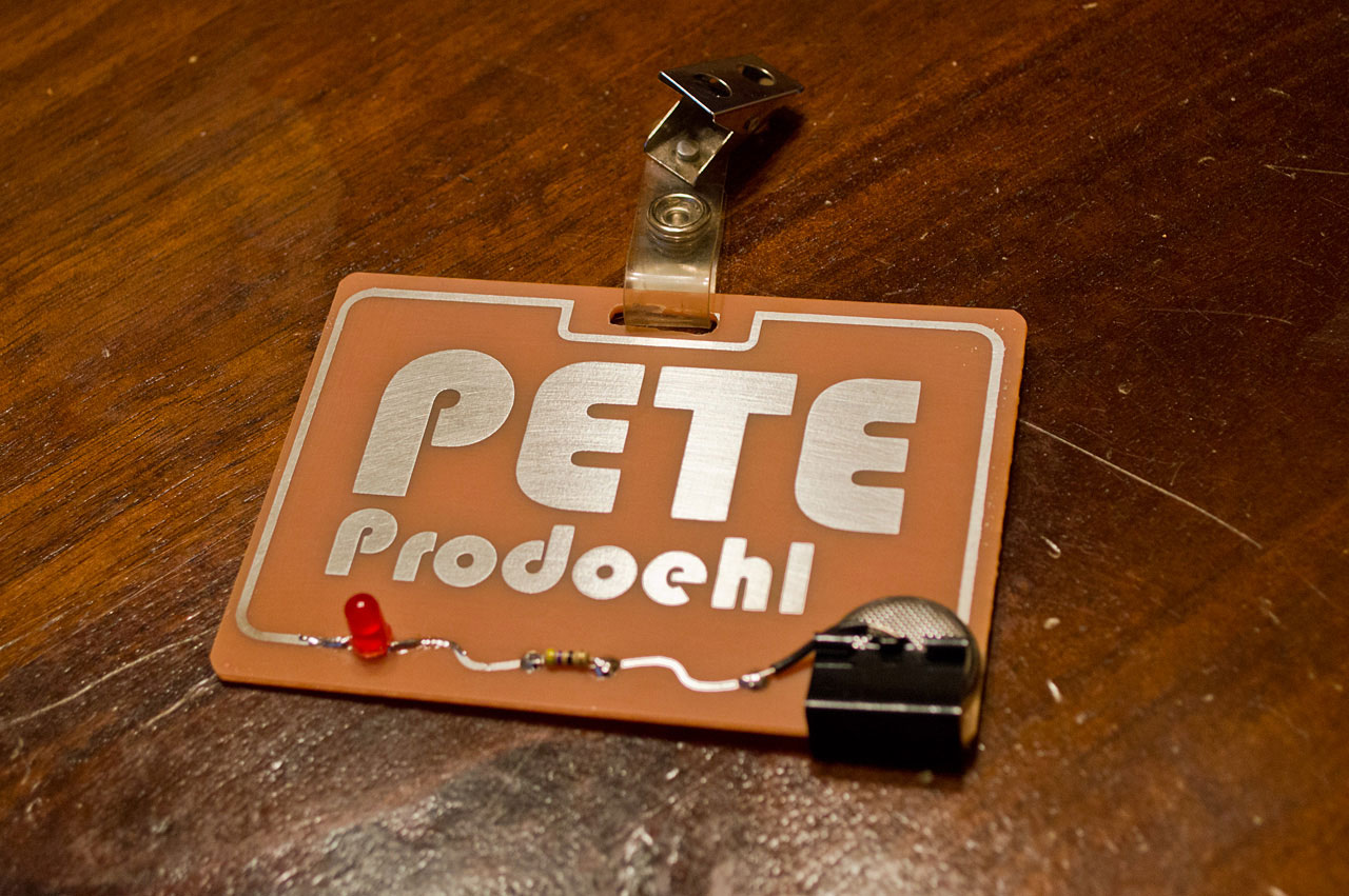
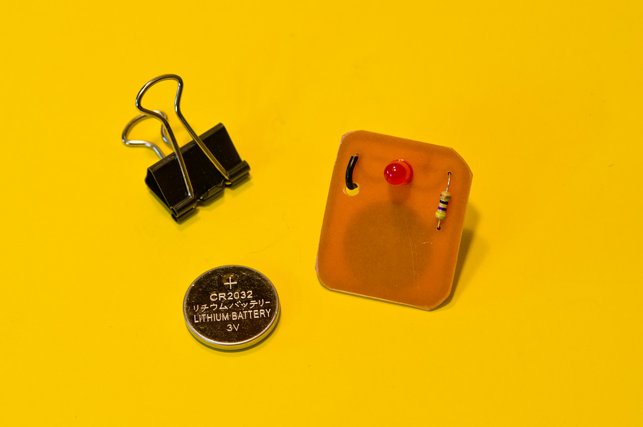
I soldered a blinking LED and a resistor in place, and since I still don’t have a tiny drill at home I went with surface mount of through-hole components, which works fine.
I also needed power, so I added a CR2032 battery and a binder clip along with a wire. The bottom of the battery (positive) goes against the PCB while the top (negative) gets a wire held against it with the binder clip. (Pretty much just borrowing heavily from the Learn to Solder Kit.)
I did end up drilling and filing a slot for the name tag clip thing, which I stole from my Milwaukee Makerspace badge.
Blink Blink! Maybe I’ll wear it to the National Maker Faire! I’ve got a few more ideas to build circuits that are one part electronics and one part art, so stay tuned!
Since I’m etching my own boards, there’s a number of steps in the process. I’ve covered it all in the photos below, and I’ll add in a bit of text to explain things.
I start with cutting vinyl on a Silhouette Cameo. Any vinyl cutter will do, this just happens to be the one I have at home. (We have the same model at Milwaukee Makerspace, and the DCRL has a much larger vinyl cutter.)
The vinyl after being cut. I’m using old scraps of various sizes, and I’ve got an old blade, and an old cutting mat, and sometimes it cuts almost all the way through the vinyl, but for this application it all works out fine.
Next is weeding, or removing all of the bits of vinyl we don’t need. I tend to use an X-ACTO knife to pick and grab off the pieces. It works well for tiny things like this.
The vinyl is all weeded and we’ve got a piece of transfer paper ready to apply. (The transfer paper sticks to the top of the vinyl just enough to pull it from the backing sheet.)
Once the transfer paper is down on the vinyl I press hard and rub it on good so it’ll adhere to all the tiny pieces.
Peeling back the transfer paper is best done slowly, checking to see if any vinyl doesn’t get pulled up. Occasionally you have to press it down again to grab a piece of vinyl that didn’t stick properly.
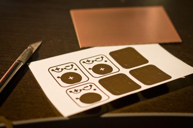
Here’s the transfer paper with all the bits of vinyl stuck to it. At this point we can stick it down onto the copper board that will be our PCB. (I usually give the copper board a light scrubbing with steel wool before sticking the vinyl on.)
Once again we press hard and rub the transfer paper onto the copper board, and then peel back slowly making sure we don’t lose any tiny bits of vinyl in the process…
And here’s our copper board with the vinyl resist in place. The vinyl works as a mask to protect the copper from being etched away. Anywhere you don’t see vinyl you won’t see copper when we are done.
Over to the PCB etching machine! It’s what we might call “janky” because I constructed it very quickly to etch some PCBs and it worked well enough that I never built a better one. I did upgrade from a servo to a DC gear motor at some point, but the bearings are still riding on smooth rods much smaller than they should be. Again, it works, so I don’t mess with it.
After adding equal parts hydrogen peroxide and vinegar to the tank (which is a food container from Noodles & Company) I put the copper board into the solution…
The board tends to float at first so I push it down with a brush. (I also use the other end of the brush to wipe away the solution while the board is etching.)
Yes, my chemical mix is hydrogen peroxide and vinegar, with a dash of salt. There are other things you can use, but this combo isn’t really dangerous, and can be easily disposed of by pouring down the drain with plenty of water. If I can avoid harsh acids, I will. It does take a bit longer to etch, but that’s where the salt comes in.
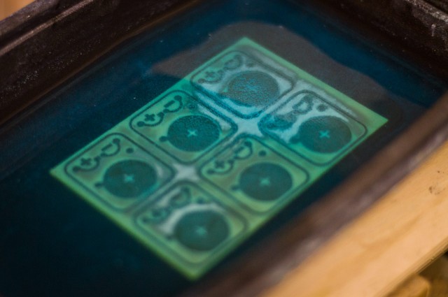
Once I start the agitation process to keep the board and liquid moving back and forth, I throw a bit of salt into the mix, which activates things and tends to foam up a bit. The foam means it’s working!
This is about 45 minutes into the etching process. You can see that the copper is nearly gone all around the edges, but not as much in the middle.
Here’s the 50 minute mark after adding a pinch more salt to the mix. It’s mostly etched but still has more copper to eat.
At about an hour and ten minutes the board is fully etched. Time tends to vary depending on if I reuse the solution or start fresh. I’m typically not in a hurry and tend to reuse solution a lot, which does take longer, but means I’m wasting less solution.
Once the board is done I pull it out and use a razor blade to gently remove the pieces of vinyl. They tend to come off fairly easy, but they are wet and stick to everything, including fingers, razor blades, the board, and anything else within 50mm of the work area.
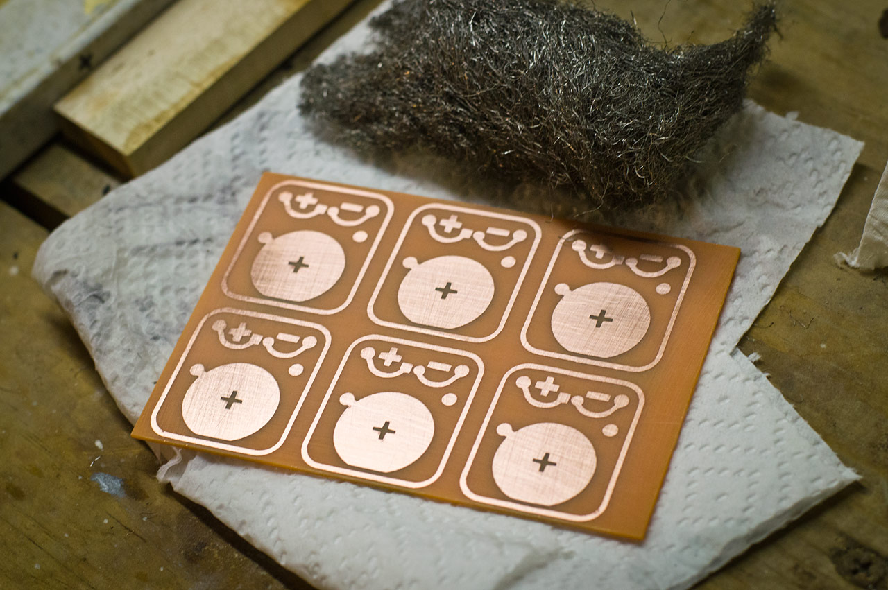
After the vinyl is removed I wash and rise the board and then dry it and give it another quick scrub with steel wool.
We’ve now got a PCB, or a “Printed Circuit Board” as they are commonly known. (Somehow almost everything I do revolves around “printing” somehow…)
That covers the etching, so the next steps are to drill all the holes and to cut the boards apart.
Oh, you’ll also want to check out this mesmerizing video featuring the PCB Etching Machine in action. Agitation is the name of the game!
This is just one post in a series, check out the other posts as well:
Some of the folks I know at UWM are putting on a symposium called Zoom Milwaukee, which will focus on craft, culture, innovation and making. They’ll also have a Maker Plaza which they described as a sort of “Mini Maker Faire” environment. They also asked if I could do a hands-on make-and-take workshop, so I decided to do a Learn to Solder activity. I’ll attempt to walk through my process for developing it in this and future posts.
Since I’ve been using Fritzing to design PCBs I thought I would play around with some ideas. The basic Learn to Solder kit tends to revolve around an LED or two, a battery, and maybe a pin of some sort. They are typically wearable badges. (Here’s a prototype and final board from Milwaukee Makerspace. Maker Shed has some nice ones as well.)
Oh, and ignore than second resistor, that was just to determine some spacing issues. Same with the battery. Fritzing isn’t the greatest tool for PCB design, but it (mostly) works and it’s simple to use. I did end up checking a version of this board with OSH Park to determine pricing and specs, but eventually I decided that this isn’t the board I wanted fabbed, and with a deadline quickly approacing I decided to go another direction.
I did use the work from Fritzing as the basis of the design I did in Inkscape though… And why Inkscape? Because my plan was to create this kit as cheaply as possible, which meant I’d be etching my own boards. I visited my friends over at ebay.com and started searching for components. I’ve ordered blank copper boards before so I got a bunch of those, and some LEDs and the appropriate resistors, and some batteries.
The evolution of design. The nice thing about etching your own boards is that you can do a few, test them out, and make some changes, and do it all again. You can do these revisions fairly quickly and very cheaply. Here’s a number of my design tweaks as I etched boards. Some things got larger, some got smaller. I needed something I could easily cut from vinyl using a Silhouette Cameo, so super-small pieces had to be avoided. The minus sign caused the most problems. You can see it change in size as we go. (The outline around each board is to assist with cutting them out.)
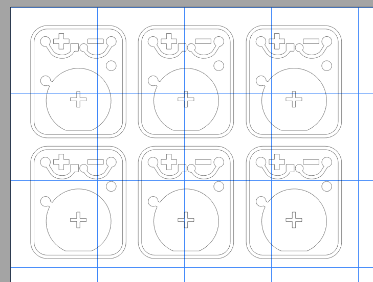
Here’s the design 6-up so I could fill a blank copper board for etching. Weeding the vinyl wasn’t a nightmare, but pulling all the tiny pieces off the final board wasn’t fun.
The copper boards I used are about 4″ x 3″ so the 6-up layout I did was loaded into the Silhouette Studio software to cut the vinyl. This worked well as I tend to have a lot of little scraps from bigger jobs to use up. (I did mention doing this on the cheap, didn’t I?)
Here’s a shot of one of the earlier design revisions with the vinyl applied to the copper board pre-etching stage. Once the etching is done all the copper you can see will be gone, leaving copper just where the vinyl is. The vinyl is the resist in this process.
This is just one post in a series, check out the other posts as well:
After a number of edits to make it “cut-friendly” and adding my own text, I used the Silhouette Cameo to cut some vinyl to use for the mask…
Since we’re going to stick the vinyl on the back side of the screen, make sure to reverse your image before you cut it! (You can do it right in the Silhouette software.)
The vinyl gets attached to the back of the screen. I don’t have a photo of the transfer paper, but yes, I needed to use transfer paper. Getting the vinyl to stick to the screen can be tricky! Go slow, very slow, and make sure it transfers ok. It may not stick very good (yet) but it will work.
Once the vinyl it in place, tape it good on at all four sides, and then add more tape. (It’s clear packing tape, hard to see in the photo.)
Flip the screen over, and press down on the screen, so it will stick to the vinyl better. Add more tape. Really, preparing screens involves a lot of tape. (The white thing on the screen is just the backing of the vinyl, which I used to save a bit of tape… It’s taped in place. Yes, more tape!)
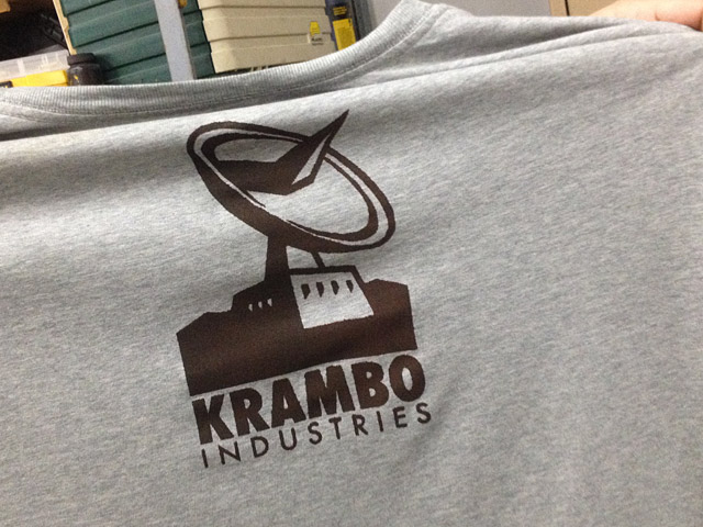
It was the first time screen printing for everyone who attended. Usually at least one or two people have had some experience (usually in high school) but this time no one had done it before. Here’s the shirt Asim printed. It turned out good!
While I only talked about printing light ink on dark shirts, Andrea brought a black shirt, which we printed with dark red ink. She said she wanted to do a bleach treatment on the shirt, which should lighten up the fabric but not the ink. Hopefully I can get a photo of that when it’s done.
I did a print on paper as well so I could add it to the “Wall of Stuff” at the Makerspace.
After I cleaned everything up I had a member ask when I’d be doing another demo/class. As usual, I don’t know the answer yet! Usually when enough people ask about it I do it. So, yeah, I’ll do it again, at some point.
It’s The Detonator! What is The Detonator you ask? Well, for Maker Faire Milwaukee we build a fire poofer, which is a device that shoots flames into the air. Workmate John McGeen started the poofer build and we finished it up at Milwaukee Makerpace. Along the way we experimented with a torch, candles, and grill igniters, until Dan the Blacksmith finally added a pilot line and some steel wool.
The Detonator went through a few revisions, but I’ll walk through the construction of it for this blog post. We brainstormed a few different ideas to trigger the poofer, but in the end I went with something simple than I knew would work reliably for the entire weekend. (And it did!)
I started by using MakerCase to design a box I could laser cut. I used 3mm black acrylic because I have a lot of it, and I made the box the size that worked with the acrylic I had. The image shows the acrylic (gray parts) and one piece of 1/4″ wood (which is tan in the image.) The wood piece went on the inside, right under the top acrylic with the hole for the button.
Since I wanted The Detonator to withstand being pressed, slammed, and pounded on by hundreds of people over the course of two days, I also built a wooden box that fit inside the acrylic box. This added strength and weight to it.
I didn’t just want a plain black box, so I added some bright yellow vinyl to it. I cut the vinyl with a Silhouette Cameo. The image above shows how I determined wrapping the vinyl around the edges.
Here are the vinyl pieces I cut. I added cut outlines around the pieces so I’d be able to line it up correctly. It worked pretty well. (I didn’t take time to measure or mark things, but that would be a recommendation.)
Above is my final “pretty” illustration of The Detonator. Below is a very black photo of The Detonator. I’m fairly pleased with how it turned out, especially since it was a rush job to build it.
There are four connector posts, but only two got used in the end. I originally had just the two in the center, but ended up splitting them and adding extra posts so I could split power between 12 volts (well, 18 volts, sort of) for the solenoid, and 4.5 volts for the grill igniters. We ended up ditching the grill igniters, so in the end I only needed one pair of connectors. Oh well!
Here’s the inside! There’s a Pololu A-Star 32U4 Micro mounted on an Adafruit Perma-Proto Half-sized Breadboard PCB with some screw terminal connectors, which is connected to a relay board. The board I used had four relays, but since we didn’t use the grill igniters I could have used a two relay board. (Also, relay boards are super-cheap on ebay.) There’s also a relay controlling a beeper that beeps a countdown. (See the video below.)
Overall The Detonator was a quick build. and there’s a few things that could have been a bit more polished. For instance, I cracked the acrylic a bit when I drilled more holes for the connection posts. In an ideal world I would have laser cut a new piece, but I didn’t have time. I also could have made the code a bit simpler after removal of the batteries for the grill igniters, but hey… The Detonator turned out good for a quick fire poofer controller!