
Some of the folks I know at UWM are putting on a symposium called Zoom Milwaukee, which will focus on craft, culture, innovation and making. They’ll also have a Maker Plaza which they described as a sort of “Mini Maker Faire” environment. They also asked if I could do a hands-on make-and-take workshop, so I decided to do a Learn to Solder activity. I’ll attempt to walk through my process for developing it in this and future posts.

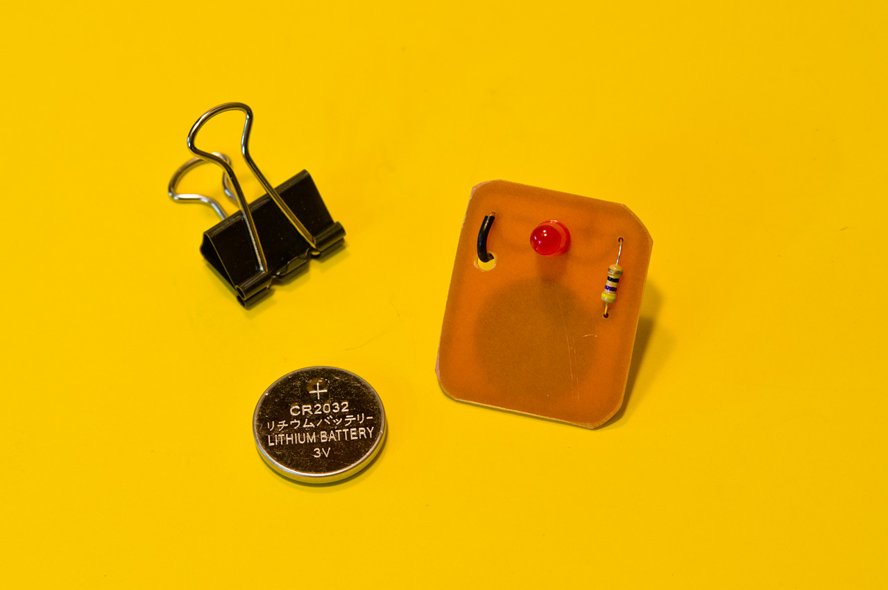
Since I’ve been using Fritzing to design PCBs I thought I would play around with some ideas. The basic Learn to Solder kit tends to revolve around an LED or two, a battery, and maybe a pin of some sort. They are typically wearable badges. (Here’s a prototype and final board from Milwaukee Makerspace. Maker Shed has some nice ones as well.)

Oh, and ignore than second resistor, that was just to determine some spacing issues. Same with the battery. Fritzing isn’t the greatest tool for PCB design, but it (mostly) works and it’s simple to use. I did end up checking a version of this board with OSH Park to determine pricing and specs, but eventually I decided that this isn’t the board I wanted fabbed, and with a deadline quickly approacing I decided to go another direction.
I did use the work from Fritzing as the basis of the design I did in Inkscape though… And why Inkscape? Because my plan was to create this kit as cheaply as possible, which meant I’d be etching my own boards. I visited my friends over at ebay.com and started searching for components. I’ve ordered blank copper boards before so I got a bunch of those, and some LEDs and the appropriate resistors, and some batteries.

The evolution of design. The nice thing about etching your own boards is that you can do a few, test them out, and make some changes, and do it all again. You can do these revisions fairly quickly and very cheaply. Here’s a number of my design tweaks as I etched boards. Some things got larger, some got smaller. I needed something I could easily cut from vinyl using a Silhouette Cameo, so super-small pieces had to be avoided. The minus sign caused the most problems. You can see it change in size as we go. (The outline around each board is to assist with cutting them out.)

Here’s the design 6-up so I could fill a blank copper board for etching. Weeding the vinyl wasn’t a nightmare, but pulling all the tiny pieces off the final board wasn’t fun.
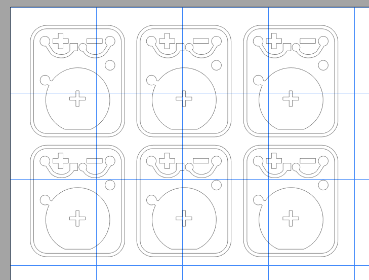
The copper boards I used are about 4″ x 3″ so the 6-up layout I did was loaded into the Silhouette Studio software to cut the vinyl. This worked well as I tend to have a lot of little scraps from bigger jobs to use up. (I did mention doing this on the cheap, didn’t I?)

Here’s a shot of one of the earlier design revisions with the vinyl applied to the copper board pre-etching stage. Once the etching is done all the copper you can see will be gone, leaving copper just where the vinyl is. The vinyl is the resist in this process.
This is just one post in a series, check out the other posts as well: