Categories
Uncategorized

#TeamArduinoCC

Arduino.cc

In accordance with a request from organizations and people I respect, here’s a photo take on 2015-04-19 showing the packaging from an Arduino UNO I purchased from Adafruit Industries (in the United States of America) on 2010-10-19 showing the text “Manufactured under license from Arduino by SMART PROJECTS S.r.l.”.

Adafruit / Arduino.cc

Here is the order information from that purchase. For more info, see the Hackaday post Your Arduino Packaging Could Sway a Court Case and the Adafruit post Please post old Arduino packaging that says “Manufactured under license from Arduino” #TeamArduinoCC.

Categories
Uncategorized

Turntable Shaft

Platter System

For my turntable drawing machine I’ll need the platter to spin. In a “real” turntable (the kind used for vinyl albums) there are three methods, idler-wheel, direct drive, and belt-drive. The illustration above shows my original idea for direct-drive, which I quickly abandoned in favor of belt-drive, on the bottom.

Rod & Bearing

Typically I use 8mm rod for things because, well, I have it handy, and lots of 608 bearings as well. For this turntable shaft, Frankie gave me some 6003Z bearings, which have an inside diameter of 17mm. I found some 17mm steel rod from McMaster-Carr, but I didn’t need very much, so I asked Chad about making a piece on the lathe. He said it should be easy if we had some stock just a bit larger, and well… Frankie did indeed have something! (Oh, if I used 17mm rod I would have added shaft collars… luckily by machining the part, we won’t need them.)

Frankie gave me a crash course in the metal lathe. (I last use a lathe back in the 1980s, and it was a wood lathe!) I learned how to face off the material, and then he showed me how to narrow it down to size. We got it to a perfect fit for the bearing!

Plastic pulley

I also had some plastic pulleys on hand from when MakerBot sold off all their old Cupcake CNC parts… I knew they’d come in handy someday! We managed to drill out the center on the lathe so it fits tight over the steel shaft. I may need to add a set screw or some locking collars, but it’s a nice tight fit right now.

Parts

Here’s the shaft, bearing, and pulley all properly sized. Once I determine the length of the shaft we’ll put it on the lathe, cut it down, and then get the other side to the right size. I’ll make some pieces that hold the bearings by either laser cutting some material, or 3D printing something, or maybe via the CNC router.

Perfect Fit!

Categories
Uncategorized

Hammer Ring

Sketch

We had a quick side project in our “Machines that Make” class which involved designing a piece of jewelry in Rhino. The piece was to be 3 dimensional, and entered into the “Rapid Jewelry 3D Printing Design Competition” put on by the Design Museum Foundation.

I’ve never really designed or made any jewelry before, but Frankie suggested I look at cosplay and wearable things for inspiration. Since I seem to have an (unhealthy?) obsession with hammers lately, I went right in that direction.

Prototypes

The hammer, like so many tools we use, is an extension of the human body, allowing us to do thing we couldn’t do with our bare hands. I wanted to celebrate the hammer as a tool and an object, and what better way than by wearing it on your finger?

Of course this hammer becomes somewhat non-functional, at least as a hammer. You can still move your fingers around to simulate the movement, but don’t expect to pound any nails with it. (There’s also a joke here about fingernails, but I’m still working on it.)

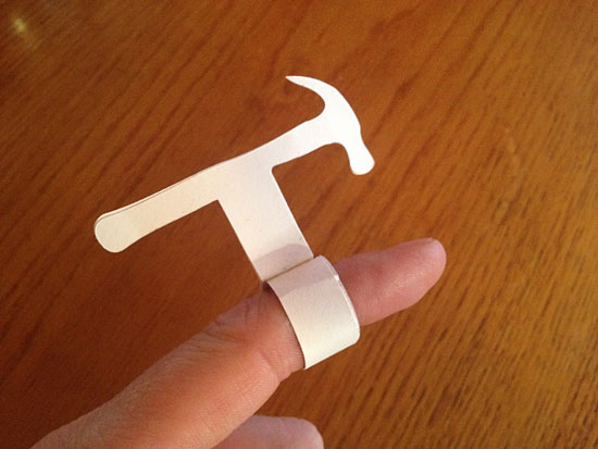
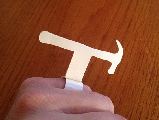
Paper Prototypes

Paper Prototypes

I did a quick sketch and then went to work doing some paper prototypes. The prototype fits well as a “mid ring” (a new term I learned) or as a pinky ring. The actual 3D modeled one should fit on my index finger.

Paper Prototypes

Imagine if you will, a whole bunch of these on one hand. Too many hammers to handle? I think not!

STL File

I learned a few new techniques in Rhino, which should come in handy. I really wish I had more time to dig into it this semester, especially the command line features. Here’s what the plain old STL file looks like. We’ve seen this view a million times before, but I also did some renderings using Keyshot which look rather nice… Check them out below!

Rendering

Rendering

Rendering

Rendering

Rendering

Obviously the 3D printed pieces won’t exactly look like this, but it was great to experiment with different materials and lighting in the rendering software. (Of course now I’m tempted to look at the open source 3D rendering applications out there!)

Categories
Uncategorized

Turntable Drawing Machine

Sketches

As previously mentioned, I’m working on a new drawing machine, and it’s based on a turntable. I’ve included some of the sketches here, as I continue to explore a few ideas.

Sketches

There’s a number of aesthetic choices to make in the design of this thing, including the material. Right now I’m focusing on wood for the majority of the build, but may also include some acrylic (which may allow for some LED lighting) and metal. I’d consider Alupanel, as that stuff is pretty nice, but it’s also a bit pricey, especially since I’d need a piece that is 19″ x 15″.

Sketches

There’s also the mechanical build to deal with. I’ve got a good idea of how that will work, and I should be prototyping the spinning platter mechanism this week. I have semi-working Arduino code already, but I’m still contemplating direct drive versus a belt system. (I have all the parts, just need to start experimenting.)

Turntable

I stopped by Bliffert Lumber last week to grab some 1/4″ Baltic Birch plywood, and I cut the top panel and turntable. These may just serve as test pieces and not final pieces, but it’s something to start working with. I used a 90 watt laser cutter as it’s quick and easy. I do have a 1/4″ end mill coming in this week, so I can cut 3/4″ wood on the big CNC router if needed. It’ll all depend on material and time. (This needs to be completed in about a month.)

Hopefully I can start working on the arm mechanism by next week, as there’s a few tricky bits involved there. I’m not sure if I will use limit switches, a servo, or make the pen placement a manual process. Hopefully a prototype will come together soon and answer some of those questions.

Categories
Uncategorized

Laser. Cut. Files. (Part IV)

It’s been a few years since I’ve posted about laser cut files, and by that I mean, the files I prepare to be used for laser cutting, so I thought I’d do an update.

Right now I typically use a few different laser cutters in the Milwaukee area. At Milwaukee Makerspace there’s a 60 watt ULS and 50 watt ULS, but using a Windows PC with CorelDraw for control, and at Brown Dog Gadgets there’s a 90 watt Chinese laser cutter using CorelDraw (and LaserCut 5.3) though it seems to be a much newer version than used at the Makerspace. I also use a 40 watt Epilog Zing at UWM’s DCRL. The Zing uses Rhino instead of CorelDraw, which may sound weird, but it works.

I’ve got a file workflow that can work with all of these machines… which I’ll explain below.

Panel Mount

Here’s what my vector art looks like in Inkscape. You’ll notice that the inside lines are blue, and the outside lines are black. This is so we can set a manual cut order for machines that don’t automatically cut inside lines first. (Some software is smart, and always makes inside cuts first, other software… is not.)

lcfiles02

I should note that while doing the design work I may end up with multiple layers. Often I’ll use layers to hold pieces or revisions of a design. For our final file though, we want a single layer.

Let’s pretend my design file is named “Panel Mount.svg”, and it has more than one layer. When I’m happy with my work, and have all the things that will be cut on one layer, I’ll save that file, duplicate it, renaming the dupe to “Panel Mount LC.svg” and then open that file. My original design file (Panel Mount.svg) is now safe and sound, but my new file (Panel Mount LC.svg) is about to get altered.

Files

I usually set all the objects to have no fill. This may not be required for all workflows, but I like to be consistent. (Oh, one more thing… you may need to “convert objects to paths” to get things to work like you expect them to in LaserCut 5.3)

Files

For the stroke I’ll set the outside lines to black… (This may be different depending on your laser cutter software.)

Files

And I’ll set the inside lines to blue. Again, this may depend on the laser cutter software & driver you use. Some allow you to set the order of colors, and some may not. If I need more colors I can use red, green, etc. (Also, if you’re working with a laser cutter operator who is colorblind, ask them what colors they prefer.)

If you want to selectively cut things and only have one color, you can use this trick: Load the file into the laser cutter software (CorelDraw, or whatever) and delete the parts you don’t want to cut, then cut. Then “undo” until all parts are back on the screen, then delete other parts, cut again, and repeat. Not the cleanest method, but it totally works. Don’t move any parts, though you may have to ungroup them, and obviously do not move the thing you are cutting.)

Stroke 0.03mm

Once I’ve applied all the colors, you can select everything and set the stroke. I set it to 0.03mm. This should set it to “hairline” when you import it into CorelDraw. Rhino also seems to do the right thing. If your stroke is too thick it can cause issues. (Always check for the lines to be set to “hairline” after you import your PDF.)

View

After you change the stroke the lines may appear very faint. If you can barely see them switch the Display Mode to “outline” which makes every stroke appear a black and sort of beefs up the lines.

At this point I run down the checklist…

  1. The file has one layer (If it had more, I duped the file and then adjusted the dupe to have just one layer.)
  2. The file has all objects set to no fill.
  3. The file has all objects set to 0.03mm stroke.
  4. The file has different colors for inside and outside cut lines.

Obviously you can do all the file prep stuff (line colors, stroke, etc.) in your master file, and then dupe that one and delete any extra layers. The order isn’t the most important thing here.

PDF Export

Once we’ve made all the changes, we can save our “LC” version of the file. After that, it’s time to use the File menu’s Save a Copy… command to save it as a PDF file. Note that “Convert texts to paths” is selected. This should create a PDF that does not rely on any fonts being installed. If you used text in your file, this is helpful. It does however mean that you cannot edit any text when you import the PDF into other software, as it will have been converted to lines.

PDF

Oh, one more thing! Some older versions of CorelDraw seem to have issues importing PDF files created in Inkscape. On Mac OS X, I just open the PDF that Inkscape created, and export it. It somehow fixes the PDF so CorelDraw likes it. Whatever… it works, so I do it!

Simple Dual Axis Solar Tracker

(BTW, the piece I used an as example was for the Simple Dual Axis Solar Tracker from Brown Dog Gadgets.)