Categories
Uncategorized

3D (STL) to 2D (SVG)

Back in 2015 I used Rhino to convert 3D files into 2D vector files that could be used in illustrations, instructions, etc. You can see what I’m talking about in 2D to 3D to 2D. Sadly, Rhino is not cheap, and I do not have access to it. Instead I would often do fake versions of this technique in OpenSCAD, which you can see in Enclosure Prototyping.

Well, thanks to Trammell Hudson, I can throw all that away! Checkout this post plotter.vision – STL to SVG and then go to plotter.vision and give it a spin.

The code is available on GitHub, and my favorite part is in the README:

I’m not a javascript programmer, so this is probably not very well written.

And yet… It exists, and it works. It may not be perfect, but the great thing about open source is that it can be improved by others in the future.

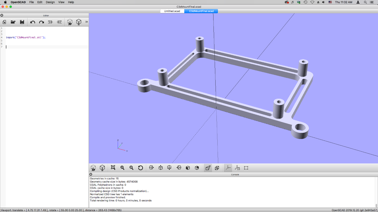
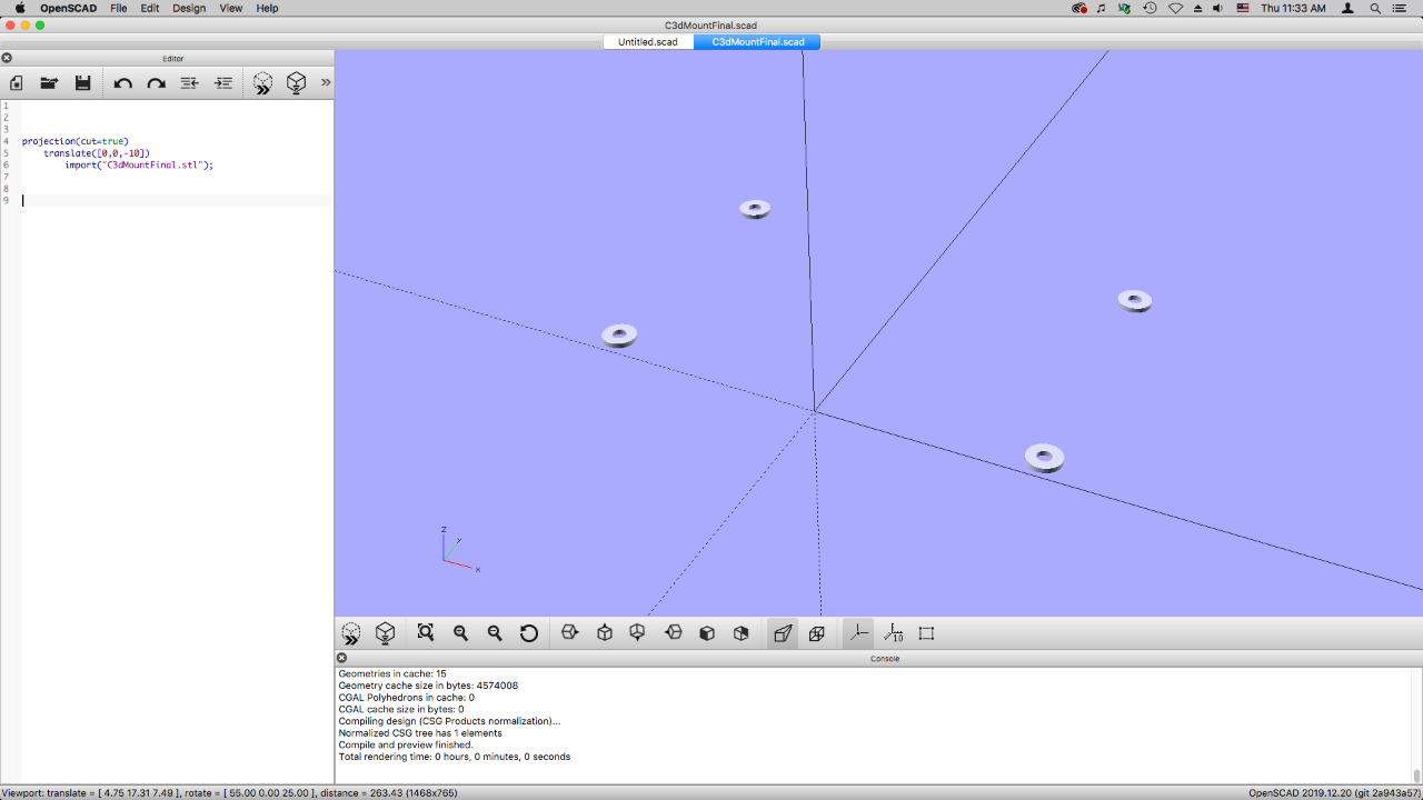
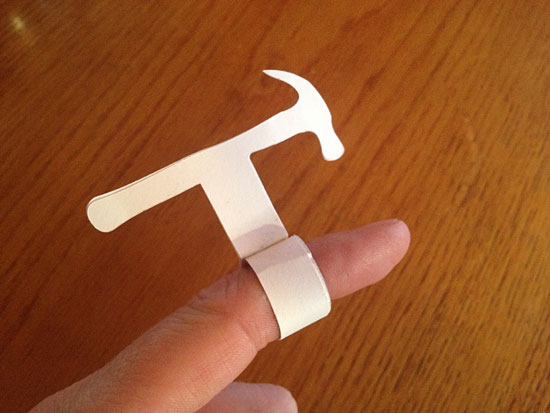
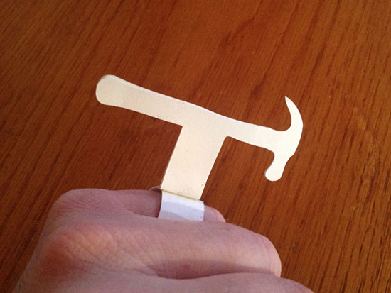
I’ve included a few results in this posts of things I’ve modeled in OpenSCAD. I think they turned out well and I can see using this tool in the future. Thanks, Trammell!

See Also: STL to SVG

Categories
Uncategorized

STL to SVG

Sometimes I need a 2D vector version of something that is a 3D model. Here’s how I do it. First, if there is an STL file, I load that into OpenSCAD.

For this model I wanted a top view so I could use the hole pattern to laser cut a mounting plate.

I select Show Axes because I’m gonna need that later…

The axes will show the center of the canvas, and luckily our model is centered…

Change the view from Perspective to Orthogonal

If you don’t know the difference between perspective view and orthogonal view, do some research I guess. (I probably learned about them in 7th grade drafting class.) Otherwise, switch between the views and it should make sense…

Okay, next I view the object from the front. Looks good!

I then add the translate command so that I can move the object in 3D space, and I lower it down, in this case 10mm, because the center line is where it will be cut.

The line projection(cut=true) then cuts a slice at the zero point in the Z axis… But we’re not done yet.

(Oh, if you choose cut=false you’ll just get the whole object, not a slice at a specific cross section of it.)

Here we can see what it looks like at an angle, which might make a bit more sense…

Let’s switch from orthogonal back to perspective view… Not required, but I’ll do it anyway.

Back to the top view… and now with the projection you can see the slice we took from the 3D model.

The next step is important… we need to Render the file! You can’t export the SVG file until you render your model.

The model will change… in this case you can see the shapes are now green with red outlines.

And now we can Export as SVG. (You could also use DXF if you need to, though that’s a garbage format I tend to avoid.)

Here’s the SVG open in Inkscape. Brilliant! I can now add to it, and my hole pattern is spaced properly for the mount I want to make. Excellent.

See Also: 3D (STL) to 2D (SVG)

Categories
Uncategorized

Hammer Ring

Sketch

We had a quick side project in our “Machines that Make” class which involved designing a piece of jewelry in Rhino. The piece was to be 3 dimensional, and entered into the “Rapid Jewelry 3D Printing Design Competition” put on by the Design Museum Foundation.

I’ve never really designed or made any jewelry before, but Frankie suggested I look at cosplay and wearable things for inspiration. Since I seem to have an (unhealthy?) obsession with hammers lately, I went right in that direction.

Prototypes

The hammer, like so many tools we use, is an extension of the human body, allowing us to do thing we couldn’t do with our bare hands. I wanted to celebrate the hammer as a tool and an object, and what better way than by wearing it on your finger?

Of course this hammer becomes somewhat non-functional, at least as a hammer. You can still move your fingers around to simulate the movement, but don’t expect to pound any nails with it. (There’s also a joke here about fingernails, but I’m still working on it.)

Paper Prototypes

Paper Prototypes

I did a quick sketch and then went to work doing some paper prototypes. The prototype fits well as a “mid ring” (a new term I learned) or as a pinky ring. The actual 3D modeled one should fit on my index finger.

Paper Prototypes

Imagine if you will, a whole bunch of these on one hand. Too many hammers to handle? I think not!

STL File

I learned a few new techniques in Rhino, which should come in handy. I really wish I had more time to dig into it this semester, especially the command line features. Here’s what the plain old STL file looks like. We’ve seen this view a million times before, but I also did some renderings using Keyshot which look rather nice… Check them out below!

Rendering

Rendering

Rendering

Rendering

Rendering

Obviously the 3D printed pieces won’t exactly look like this, but it was great to experiment with different materials and lighting in the rendering software. (Of course now I’m tempted to look at the open source 3D rendering applications out there!)

Categories
Uncategorized

2D plates from 3D objects

brocstl001

One of my, uh, “hobbies” is figuring out alternative workflows, or ways of solving a specific problem. I often do this with a bias towards open source or free software, because I like to know how to do things, and share how to do things, even when you don’t have expensive commercial software.

If you remember reading about Broc’s model in one of my Digital Fabrication posts, he mentioned using the “Unroll Developable Srf” function in Rhino to create flat pieces. Well, I have access to Rhino at UWM, but any piece of software on my own machines is preferable because I have easy and immediate access to it 24 hours a day, 7 days a week.

Broc's STL in 123D Make

With this in mind, I set about trying to do what Broc did, without using Rhino. I ended up using 123D Make from Autodesk. It’s not open source, but it’s (mostly) free if you’re willing to create an account and share your personal info.

Broc's STL in 123D Make

123D Make has a bunch of nice options for breaking 3D objects into “slices” that can be assembled using various methods. (Supposedly there’s a beta version that does finger joint boxes.) It took a bit of tweaking things, but I was able to create slices just like the ones Broc made in Rhino.

Broc's STL in pieces

The output from 123D Make was a vector-based PDF file with all the parts in 2D.

Broc's STL in pieces

The PDF was easily imported into Inkscape, where it can be set up for being cut by a CNC machine. There’s a minimal amount of clean-up needed to remove any attachment tabs that the application generates. Try as I might, it did not allow me to put a value of zero on some of the parameters. Maybe in the next version. :/

(Oh, you could always print out paper templates and cut things the old fashioned way if you’re not a CNC user.)

Here’s a great promo video 123D Make that shows some of the slicing capabilities.

Categories
Uncategorized

stlviewer canvas adjustment

STL Viewer

I use Gary Hodgson’s stlviewer quite a bit, as it allows for a quick view of an STL file in your browser, and since I’ve always got a browser running, it’s often easier than launching yet anther app just to view a 3D model.

But one of the things that’s always bugged me about it was the fact that the build plate appeared to be 100mm x 100mm, which would be fine in 2010 if using a MakerBot Cupcake, but my RepRap has a 200mm x 200mm build surface…

STL Viewer

This is much better! My models over 100mm long/wide actually fit on the build plate instead of spilling over into space. Obviously if you’re using Gary’s online version you can’t really make changes, but I just run it locally from my hard drive, so I can easily hack at it.

STL Viewer

Just go into the js folder and in there is the thingiview folder, and open thingiview.js in your favorite text editor. Line 711 should look like this.


plane = new THREE.Mesh(new Plane(100, 100, 10, 10), 
  new THREE.MeshBasicMaterial({color:0xafafaf,wireframe:true}));

(Note: It’s all one line, but it’s wrapped here for readability.)

For the part that says new Plane(100, 100, 10, 10) just change it to new Plane(200, 200, 10, 10) and you’ll get a 200mm x 200mm canvas with which you can display your lovely STL file on.

(Obviously if you’re using MegaMax you should go a bit larger, perhaps 300mm x 300mm would be appropriate.)