Categories
Uncategorized

What is Digital Fabrication and Design? (Part III)

What is Digital Fabrication and Design?

The first artist we had visit UWM for this year’s Artist Now! talks was Charles Beneke. His work tends to be in the areas of print-making and multi-media, but he did mention that he’s used laser cutters for some of his work.

Here’s part of his talk where he mentions using laser cut pieces:

Charles seemed to indicate that the laser cutter was just a way for him to speed up production. This isn’t the first time I’ve heard this from an artist. Many artists seem to look for ways to make their current process easier, or faster, or both. Instead of cutting things by hand, they want a machine to cut them. Most of these artists don’t seem to view the laser cutter as a unique and primary tool to create work, but just a more advanced method of what they’d do anyway, with their own hands and a sharp blade.

Charles Beneke

In most cases though, these artists (and designers) are digitally designing things, and then using CNC machines to do at least a part of the production process, though I’m not sure any would say that they are working in the area of Digital Fabrication and Design.

(Previously: Part II, Part I)

Categories
Uncategorized

Vector to Raster and back…

Encoding Discs

While Inkscape is a great and powerful open source vector editing application, sometimes it can’t do it all. Since I primarily use it for creating files for laser cutters, vinyl cutters, the Egg-Bot, etc. I need to have lines. No fills, no objects sitting on top of other objects, no crazy intersections of paths, just lines.

I’ve found that on occasion it’s actually easier to export a raster image, re-import it, and trace it to get the needed vector file. I’ve done this for many files from OpenClipArt.org because they weren’t created with CNC uses in mind, but that’s what I use them for.

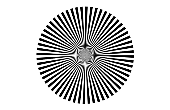
Back when I wrote my rotary encoding post I mentioned a perl script that could create encoding disks. It’s simple to use, and outputs an SVG file that I can open in Inkscape. Sadly, it’s not exactly what I need, but it’s pretty close, and easy to fix.

Encoding Disc

Here’s the disk that was created, which uses some neat SVG capabilities to generate it, but makes it quite difficult to edit using Inkscape. You can’t ungroup it, or break it apart, or use union or difference commands on it.

Encoding Disc

I’ve placed a smaller disk on top of it, Right now it’s gray (just so you can see it) but I’m going to fill it with white and give it no stroke. (Normally I would place one object on top of the other and use the difference command to cut a hole in the larger object. In this case, that can’t be done.)

Export at PNG

Once that’s done it looks like I want it to look, but it’s not all lines. It’s really overlapping objects. As long as it looks like I want it to look, I can export it as a bitmapped file. (A PNG file, to be precise.)

Import PNG

Here’s the PNG file. It’s raster, not vector, and again, it looks just like I want it to look. Excellent! Let’s go back to Inkscape and import the PNG file.

Trace Bitmap

Once imported I can use the Trace Bitmap command to easily change this black and white image into a vector file. (Yes, make sure it’s just pure black and white, so it can easily separate the two colors and create the needed path.)

Outline

After the bitmap has been traced I’ve got nice vector lines, shown here in outline mode, and it’s ready to be cut with a CNC machine. (Oh, I’ll probably add a center mounting hole, as the encoding disk eventually does need to attach to something.)

Categories
Uncategorized

Single Stroke Font

I needed a single stroke font for some laser cutting. You’d think that would be an easy thing… Well, keep reading.

When laser etching, any font could be used. You can raster etch the type, or “vector etch” the type. Raster etching takes a long time, and vector etching (basically doing a low-power vector “cut”) is fast. If you’re doing 3,000 pieces, the time can make a huge difference!

Regular font

Here’s a normal font in Inkscape. Fonts consist of an outline which is then filled with a color. In this case, the outline of the font is filled with black and you see what you normally see when viewing a font on a computer screen.

Regular font

Here’s the normal font with the fill set to none and the stroke (outline) set to a thin line. You could laser etch this (and some people do) but you’re now outlining the letters instead of just etching them with a single stroke. This is fine, but takes more time. Since going really fast is our goal, this doesn’t work.

At this point, you may be thinking “No problem! Our pals at Evil Mad Scientist Laboratories have us covered with Hershey text, and engraving font!” Indeed, Hershey text is awesome, but not always the right solution. I use Hershey text often, and it’s lovely, but let’s keep exploring…
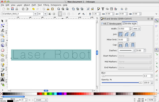
CamBam font

I found these CamBam fonts, which probably work quite well for a spinning bit that is cutting material, but there’s an issue:

All the fonts are built using a 100% overlap in the font design, which tricks my TrueType font design program into thinking they are really looped TrueType fonts, when they really don’t have an inside and outside loop.
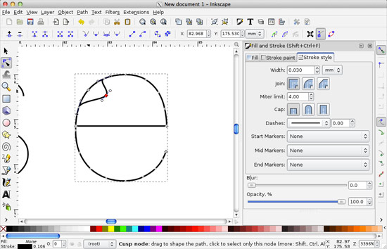
CamBam font

A spinning bit cutting material is quite different than a laser cutting material. If you use this font to laser etch, it will double up, which mean you’re lasering the same thing twice. This takes longer, and cuts your material twice. No good.

You can manually go in and delete the overlaps, but it’s a time-consuming pain, and you’ve got better things to do.

Machine Gothic

I found Machine Tool Gothic, which looks a bit weird when you first select it, but we’ll fix that. Remember that fonts are typically outlines that are filled with a color. That’s what is happening here.

Fixing Machine Gothic

We just need to set the fill to none, and give it a thin stroke. Much better! We’ve nearly got our clean single-stroke engraving font.

Fixing Machine Gothic

Let’s fix the weird lines that connect everything and close the paths. First you’ll want to convert the type to outlines (that’s the “Object to Path” command in Inkscape) and then select the two nodes at each end of the line you want to delete and use the “Delete segment between two non-endpoint nodes” feature to remove the line.

Fixing Machine Gothic

Oh, it’s worth noting that when you convert the type to paths, you lose the ability to edit it as type. More on that later. Here’s the “L” with no extra line connecting everything.

Now, it may look like only certain letters need the extra line deleted, but they all do. Go through each letter to delete the extra lines! If you’re doing a one-off project this may not matter as much, but if we are laser cutting 3,000 pieces, even an extra 5 or 10 seconds per piece will make a huge difference.

Type on a curve

Here’s the real reason I wanted to use an editable typeface rather than the Hershey text extension. With text, you can place it on a path. This means you can curve the text onto a circle or some other shape. We want to make sure we’ve got the text exactly as we want it before removing the extra lines. (Remember that we need to change the editable type into outlines before we remove those extra lines.)

Type on a curve

Don’t forget to remove the circle, or whatever path you used to place your text on.

Type on a curve

Fire up the laser! Here’s our clean and ready to vector-etch single-stroke type.

Categories
Uncategorized

Art Robot (It’s a thing.)

Havey Moon's Drawing Machine 1

Harvey Moon‘s been at this longer than I have, and he’s been an influence for years. This video is excellent, and says much of what I’ve been thinking about recently.

One of things I’ve said about my own drawing robots is that the “performance” they create while functioning is a part of the art.

From Harvey:

“When I show this machine it’s a performance. It’s the machine performing and generating the work, and that to me is the art.

Are the drawings the art, or a by-product of the performance, or documentation of the performance?

I’m also focusing on the design of the robots. This is the ‘Digital Fabrication and Design’ side of things. The robots are objects. I create them by using software to designing them, and then using CNC machines to create the various pieces, and then assembling them.

There’s sort of a lot going on, I just need to organize it all.

Categories
Uncategorized

Infrared Proximity Sensor (Mount)

GP2Y0A41SK0F

The Sharp GP2Y0A41SK0F is an infrared proximity sensor. You can grab them from SparkFun, Pololu, or many other vendors. (There’s a bunch of different models, but I’m using the GP2Y0A21YK right now. The GP2Y0A21YK appears to be roughly the same physical size.)

If you’re using it with an Arduino, Jeroen Doggen has a nice library called Arduino-distance-sensor-library (which should be easily extendable). It’s just a few lines of code to read distance in Centimeters, so it can be used for robotics or physical computing projects quite easily.

Distance Sensor Mount

Since I’m using this sensor, I needed a way to mount it. As usual, I look around for a datasheet. Datasheets will often contain the technical drawings of a part. If you’re lucky, they’ll be vector based (Hello, Inventables!) but if not, you can still use them to determine the dimensions of things, or where mounting holes need to go.

Sharp GP2Y0A41SK0F Analog IR Distance Sensor

Often I’ll pull a datasheet into Inkscape, put it on the bottom layer, lower its transparency, and draw on top of it. Sometimes that works, and sometimes you just need to pull out the calipers and take a few measurements. In an ideal world, all vendors would release technical drawings of their products in vector formats. (Well, at least in my ideal world.)

Distance Sensor Mount

You may notice that some of these parts look familiar. Indeed, I grabbed part of the motor mounts from my FND upgrade.

Distance Sensor Mount

Oh, I should note than I want this sensor mounted on the inside of things. If you want it mounted on the outside, you really just need two holes for the mounts, and maybe one for the wires.

Distance Sensor Mount

If you were wondering about that part with the notch, that’s to make the sensor level while mounting it inside, and the notch is for the wire connector.

One more note on the mounting holes. They are 3.2mm in diameter, which means using a 3mm screw would make sense, but I only had Imperial hardware handy. I also only had 6-32, which is 3.5052mm in diameter, and no 5-40 which is 3.175mm in diameter. No worries, since the sensor is plastic, a quick shave with an X-ACTO knife on the inside of the holes made them fit quite easily.

At some point I’ll need to test how multiple sensors react to each other in the same physical space… That should be interesting!

Note: You can find it on Thingiverse and YouMagine.