Categories
Uncategorized

Controlling the Controller Cheaply

PCB

Hey, it’s only been six months since my last post about motor controllers and the Power Racing Series so I guess it’s time for an update! If you missed it, I’m working on a tiny electric vehicle that can serve as a reference for teams of beginners to build their own.

Controller

In the last post I talked about a cheap motor controller that required an expensive throttle and alluded to a method of using a cheaper throttle… here is that method.

I started by asking questions on the Power Racing Series Google Group, and people much smarter than myself offered advice, and that’s where I learned about digital potentiometers. I ended up testing my idea with help from this tutorial and eventually got an MCP4131-104E/P-ND digital potentiometer (for less than $1.00) and paired it with an Arduino Nano that was less than $2.50 to create a converter that allows a cheap throttle to be used with a cheap controller.

If at any point you feel like saying “Hey dummy! You should have done it this way!” feel free to leave a comment. Most of my crazy pursuits involve me learning a lot along the way, and this is no exception, so I’ll keep going.

Controller

After I had a working prototype on a protoboard I decided to design a PCB because I’ve been working on getting better at PCB design for the last two years now, and it’s sort of fun (and challenging!) This is the most complex board I’ve worked on so far, and of course, mistake were made…

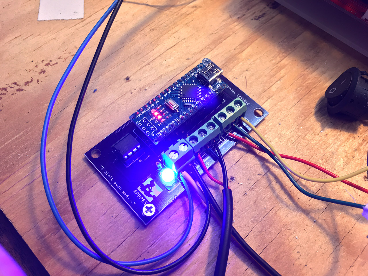
First of all, see those wires coming off the board? There should be screw terminals there, but I was unaware that the holes were the wrong size and the pins of the screw terminals did not fit. Argh… wires will do for now.

Controller

Everything wired up and ready to go! Except, it didn’t go… Seems I managed to not quite route everything the right way. Back to the drawing, and tracing all the connections with a meter, and I discovered a connection that shouldn’t be there…

Controller

…but that’s what Dremels are for! I was able to cut the trace and get it working. Back to the computer to make a few changes to the PCB. (And yes, I am still using Fritzing. I’ve gotten used to it, and know how it works, so… okay then.)

Controller

A few weeks later I got a new version from our friends at OSH Park and this one fixed the issues and worked! I should still get similar screw terminals but hey, it does what it should do, so that’s something.

You might notice some of the analog pins and some ground connections broken out at the front edge of the board. There are for future enhancements. It would be fairly easy to add in “cruise control” (for parades) or a speed limiter, perhaps with a keyed switch, to allow kids to drive the vehicle safely. (Again, people smarter than me.)

Controller

Whomp! Here’s my “breadboard” showing everything. Batteries to power the motor, and a buck converter to drop the voltage to 12v for the Arduino and a cooling fan. The throttle connected to the converter and then to the motor controller to control things. We’ve also got a DPDT (double-pole, double-throw) switch in there to allow for forward and reverse to the vehicle, and a kill switch, fuse, and voltage meter. Basically all this will need to be jammed into the vehicle to control it. (Don’t worry, we’ll be using larger batteries, thicker wire, and a larger motor.)

Controller

Here’s the controller with a cooling fan mounted to it. I’ll provide files to laser cut or 3D print the mounting pieces, or templates to cut by hand, which is totally doable. (I learned the hard way last year that if not properly cooled the capacitors on these controllers can blow.)

Controller

I also added a bright blue LED to the board (you can choose another color) to indicate when it’s receiving power. Another suggestion I got from someone. I’m sure there is still room for improvement (like, you know, diodes) but hey, it works and I look forward to testing it.

Update! Here is some Arduino code.

Categories
Uncategorized

Teensy Breakout Board v1.4

You may remember version 1.3 of my Teensy Breakout Board, and some of the planned improvements I mentioned. Well, it’s a year later, so I should probably get around to actually talking about it.

I finished v1.4 last year, and I even had a bunch of them made via Seeed Studio’s Fusion PCB service, and they turned out great. We’ve been using them for numerous projects, and just recently I finally got around to the protective fix I added in v1.4.

Teensy USB Protector

I modeled this tiny part and 3D printed it. It’s got a hole for a screw, and two slots for zip ties. The photos below show the rest.

Teensy BOB v1.4

Teensy BOB v1.4

Teensy BOB v1.4

Teensy BOB v1.4

Okay then, the chance of the Micro USB connection getting ripped loose from the Teensy has been reduced quite a bit! The zip ties hold the cable end in place to the plastic piece which attaches to the fifth hole on the PCB. I’m looking forward to never have to see another Micro USB jack ripped loose.

Teensy BOB v1.4

Oh, and one more thing… I ran into Jasmine during Maker Faire and we talked about Tindie, and somehow she convinced me to start putting things up there, so now the Teensy BOB v1.4 is available on Tindie in case you want or need one.

Categories
Uncategorized

ATtinyNoisy

ATtinyNoisy

I needed some small boards to put an ATtiny85 on, so I drew up a simple board in Fritzing and had them made up at OSH Park.

ATtinyNoisy

Here’s the breadboard view in Fritzing. Whenever I need “holes” to solder random components into I just use screw terminals. I’m sure there’s another/better way, but I’ve not found it yet, so I keep doing it this way.

ATtinyNoisy

Once the breadboard view is done, I go to the PCB view and move things around, make all the connections, and then export the files in Gerber format. Once you have a folder of Gerber files, you can ZIP it up and then upload to OSH Park for fabrication. (I covered this process in a previous post.)

MCN Gerber Viewer

I did find this Mac OS X application called MCN Gerber Viewer which allows you to view Gerber files. You can view the different “layers” and turn them on and off to check your board before fabrication. OSH Park shows you what your board will look like when you upload it, so you can easily check for issues, but MCN Gerber Viewer is still handy to have around to check files before you upload them.

You can download ATtinyNoisy, which includes the Fritzing file and the Gerber files, or just order it from OSH Park.

Categories
Uncategorized

Teensy LC BOB v1.3

Teensy LC BOB v1.3

Update: If you’d like one of these boards, there’s a newer version of this board, and you can purchase it on Tindie.

Good News, Everyone! The new Teensy LC break-out board is ready! Yes, we’re now at version 1.3 of the Teensy LC BOB.

Preview

I’ve made a few changes since version 1.2. I moved the traces from the top to the bottom (how did I miss that!?) and I added an extra ground line so that you can connect a bunch of screw terminals to the ground row even if you don’t solder in header pins at the end of the board and only do the sides. (This also comes in handy if using the Teensy Audio Adaptor Board.)

I’ve also lengthened the board a bit, and added a fifth hole, and here’s why…

Installed

For a recent project I discovered that the USB cable was able to rip the USB connector right off the Teensy if hit, twisted, or yanked in the wrong direction. The fifth hole is for adding a piece (wood? plastic?) by screwing it into the bottom and then looping a zip tie around the USB cable for strain relief.

USB mock-up

I scanned in a Micro USB cable and placed it over an image of the board to figure out spacing. It should work. I may end up 3D modeling the piece that holds the USB cable in place.

As I use the boards more I may find other improvements along the way. Also, I’m now able to load in custom images and graphics onto the PCB, so I’m already scheming for my next OSH Park project.

Categories
Uncategorized

Teensy LC BOB v1.2

Teensy LC BOB v1.2

Update: If you’d like one of these boards, there’s a newer version of this board, and you can purchase it on Tindie.

Woohoo! My new boards came in from OSH Park. The Teensy LC BOB v1.2 looks good! It’s purple, it has labels, it has places to put screw terminals and holes for mounting… There’s even a version number now.

Teensy LC on Perma-Proto Board

If you saw my previous post, I mentioned how I was doing things, which looked a bit like the photo above. There’s nothing wrong with this, but I wanted it a bit cleaner, hence the Teensy LC BOB PCB.

Teensy LC BOB v1.1

Here’s a photo of one of the v1.1 boards in an interactive museum exhibit. I had to drill the holes a bit larger to get it mounted, which is the reason the new version is v1.2.

I’m still not totally sure about the pin I labeled “17v” as it could be mistaken as “17 volts” but it’s really “pin 17 at Vin voltage”. This means the thing labeled “17v” will be whatever your input voltage is… and if you plan on using Neopixels, it should probably be 5 volts. I’ll assume users can read about the Teensy LC and figure it out.

OSH Park

And hey, you can order this PCB now! Get it from OSH Park. It’s shared publicly on the site. There doesn’t seem to be a way to set a license on OSH Park, but I’d consider it Open Source Hardware. If I had known how to add the OSHW logo, I would have. (Of course the Teensy itself is not open-source, but hey, not everything can be. It is a great piece of hardware, though!)

Note: The needed screw terminals are 2.54mm pitch, so these or these will work.