Categories
Uncategorized

The Moxie Board

Moxie

A large part of the Power Racing Series is Moxie. Moxie is best described as, being awesome. The crowd gets to vote for your car using the Moxie Board. Each button press equals a vote. Being fast is one way to get points, but another way is by being awesome… so, Moxie.

Above you’ll see a photo of the official Moxie Board used by the series. Since we also had a PPPRS race during Maker Faire Milwaukee, which overlapped the race in New York, we had to build our own Moxie Board, so here’s what we did…

The Moxie Board

It looks fairly similar, but it’s a bit smaller and lighter than the original, and it’s got 24 buttons instead of 30 (though I believe the original was recently expanded to have that 30 buttons. Who knew there’d ever be that many cars in a race!)

I got some Coroplast from Midland Plastics for super cheap, and they didn’t have any wide enough, so the black strip running down the center is gaff tape used to hold two pieces together to be wide enough. I then found some scrap wood in the shop at work which was long enough, but too skinny to be used for anything else, and built a simple frame with some small blocks of HDPE in the corners to hold it all together. (I was told the reduced weight of this Moxie Board was a big plus.)

The front is screwed into the wood frame, and the back is held in place with some VELCRO® hook and loop so we could open it to get to the electronics…

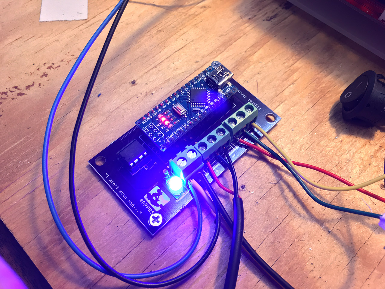
As for the inside and the electronics, while the original uses an Arduino Mega with a Bluetooth module to send real-time updates to Patrick’s Android phone which is running some special app, I chose to do it differently.

moxie-board-04

I’m using a Teensy 3.5 which has plenty of input pins and a built-in MicroSD card slot. The way it works is simple, each button represents a number from 1 to 24, and when pressed, the Teensy gets the value of every button, with the ones not being pressed equal to 0 and the one being pressed equal to 1, and then writes it to a file called MOXIE.csv. When the race is over you just put the MicroSD card in a card reader and import the CSV file into a spreadsheet and grab the last row. (Hopefully your spreadsheet is set up with the names of the cars in the corresponding columns.)

In testing, this all worked fine, but obviously the real world had to come along and crush my hopes and dreams…

moxie-board-05

Failure #1: Because the Teensy is a low power device, it doesn’t draw much power from the USB battery pack we were using. I’ve seen this before, so I use a battery pack with a built-in LED “flashlight” that stays on, as long as you press and hold the button when turning it on. I told this to two people, but forgot to write instructions to put inside the Moxie Board, so there’s a chance this was not done properly and power was lost. (There is an indicator LED that lights up when a button is pressed, but not a “POWER ON” LED which would have helped… maybe.

Maybe Failure #2: It could be that my code isn’t quite right. I do not have the most recent code that the official Moxie Board is running, but I have an older version that may be close. My code is a little different, but should yield the same results… I think. This is worth checking on.

I also do not have a good way to attach Moxie Labels, so they are just attached with tape or Hook and Loop for now. Ran out of time for anything better. :/

One more note! In the photo there’s a bunch of green wire and LEDs attached to the front of the Moxie Board. Those were added for the night race. All the actual wiring for the Moxie Board is located on the inside.

moxie-board-03

I’ve heard of one other group working on a Moxie Board that will use a Raspberry Pi, which I thought about doing as well, but ended up choosing a Teensy instead. As we add more races, we’re going to need more boards, so I’m hoping we see more ideas and eventually come up with even better ideas. (Note that I wanted to stay simple because simple gets done while over-complex builds, while fun, don’t always get finished, or work properly. But then, who am I to talk!?)

Categories
Uncategorized

Wheels of Improvement

In our last post about the Power Racing Series which was aptly titled Wheels of Fail, we talked about the crappy Harbor Freight wheels and how they sometimes explode (not really) and ways to strengthen them. This time we’ll focus on adapting them to a 1″ live axle setup.

If you’re not sure what a “live axle” is, it describes a setup where the entire rear axle spins and (at least) one wheel is attached to the axle to spin with it. Here’s a good description.

Let’s get some parts! Over at BMIKarts there’s a 1″ live axle at around $25 (depending on length) and you’ll also need a 1/4″ Keystock that is used in the Keyway of the axle to hold the wheel in place.

Harbor Freight Wheels

Okay, let’s get some wheels! Sadly, the $4.99 Harbor Freight wheel now seems to be $5.99. With a 20% off coupon it comes in around $4.80. You’ll need two wheels for this setup, so budget $9.80 for our drive wheel. (But you’ll have a spare tire and inner tube.)

Harbor Freight Wheels

Here’s our Harbor Freight wheel. It’s got (poor quality) bearings and ready to fit on a 5/8″ axle, but since we’re using a 1″ axle we need to make some modifications. Oh, make sure you let the air out before you take it apart!

Harbor Freight Wheels

Remove the four bolts and throw them away. Well, you can save them for something, but on one wheel there were the thinnest washers I’ve ever seen, and the other had no washers. The bolts are too short so we won’t be using them. You’ve got the tire and inner tube and two rims…

Harbor Freight Wheels

Get rid of the rim with the extension tube on it, and use the shorter rim from the second wheel. You got two, remember? Did you take them both apart? Good! You did it right!

Harbor Freight Wheels

There’s one more thing we’ll need. The Galvanized Wheel Hub with (4) 5/16″ Bolts on a 2-13/16″ Circle (1″ Bore) for $13. You can get the version with no hardware. I got the version with 5/16″ jam nuts, so I had to knock them out with a hammer. (A few light taps were all that were needed.)

Depending on your setup you might want a different solution. The Harbor Freight wheels work with a 2-13/16″ hole pattern, so use that. And if you don’t use a 1″ axle, choose what matches your axle.

Harbor Freight Wheels

I put some 1/4″-20 bolts on the hub along with some washers and nuts. (You might want grade 5 steel or something a bit stronger than your typical hardware store bolts.)

Harbor Freight Wheels

Put it all together! Take that hub, stick it through the rims, and don’t forget the tire! You’ve got a drive wheel all ready to go on your 1″ live axle.

Harbor Freight Wheels

Make sure you put the air stem on the right side. You can’t access it (and it won’t fit) on the side with the hub. (Which is why we needed two of the short rim pieces from two different wheels.)

Okay, so we’ve now got a drive wheel for a 1″ live axle that was under $25 to build, and required no drilling or cutting or specialized tools. We’ve also got a spare tire and inner tube. We’ve still got to modify the other rear wheel, which will (hopefully) spin freely with some bearings, but that’s a post for another time. (Also, we still have to figure it out!)

Categories
Uncategorized

Wheels of Fail

Fail

One of the rites of passage for the Power Racing Series is to use the cheap Harbor Freight wheels on your car. When you can get the whole thing, tire on a rim with a hub and bearings, it’s quite appealing. Also, the tires can be as cheap as $5.00, and that’s before you use a coupon. (I should mention the bearings are crap, and those should probably be replace. Still, you can easily start with them!)

In case you can’t tell from the photo above, they are sort of terrible. Cartastrophe used them their first race and got to experience what it’s like when your car goes one direction and your wheel goes another direction. This is a (somewhat) common occurrence, and it’s always hilarious (when it happens to someone else.)

Harbor Fright!

But! Hacker and Makers and Those Who Scrounge and are Cheap often enjoy the challenge of modifying things to do what they were not supposed to do. Like making wagon wheels handle the lateral forces of sharp turns at 20 miles per hour.

Over the years team have added in gussets, reinforced the rims with steel plates that have been drilled out for the axle and bolts, some teams have 3D printed pieces to strengthen the rims (which actually worked!) and at least one person mentioned how they use a piece of “laser cut steel” and I’m like… wut? Yeah, hackers…

So there are options, and there are always options. I mean, check out the crazy hub story from Tom at Milwaukee Makerspace!

A Better Rim Job

While thinking about an easy and cheap way to strengthen the rims I was wandering around the hardware store and found the flange you see above, which was less than $4.00. Now, it doesn’t quite fit properly. I mean, I’ll need a larger hole for the axle. With a 1″ axle I’m hoping a 1″ pipe flange hole will work, though we may have to file down or drill out the threads. The bolt holes do not match, but drilling out the holes on the rim might be the solution to that, and maybe switching to 1/4″-20 bolts…

There are also PVC flanges that may work. Those might prove easier to drill out, though the iron flanges are still less than $5.00 and can be found locally.

If you’ve got an idea how to easily and cheaply use a COTS part to solve this problem, let us know! It should require minimal modifications, hopefully just drilling and filing, and not involve laser cut steel. ;)

Categories
Uncategorized

Controlling the Controller Cheaply

PCB

Hey, it’s only been six months since my last post about motor controllers and the Power Racing Series so I guess it’s time for an update! If you missed it, I’m working on a tiny electric vehicle that can serve as a reference for teams of beginners to build their own.

Controller

In the last post I talked about a cheap motor controller that required an expensive throttle and alluded to a method of using a cheaper throttle… here is that method.

I started by asking questions on the Power Racing Series Google Group, and people much smarter than myself offered advice, and that’s where I learned about digital potentiometers. I ended up testing my idea with help from this tutorial and eventually got an MCP4131-104E/P-ND digital potentiometer (for less than $1.00) and paired it with an Arduino Nano that was less than $2.50 to create a converter that allows a cheap throttle to be used with a cheap controller.

If at any point you feel like saying “Hey dummy! You should have done it this way!” feel free to leave a comment. Most of my crazy pursuits involve me learning a lot along the way, and this is no exception, so I’ll keep going.

Controller

After I had a working prototype on a protoboard I decided to design a PCB because I’ve been working on getting better at PCB design for the last two years now, and it’s sort of fun (and challenging!) This is the most complex board I’ve worked on so far, and of course, mistake were made…

First of all, see those wires coming off the board? There should be screw terminals there, but I was unaware that the holes were the wrong size and the pins of the screw terminals did not fit. Argh… wires will do for now.

Controller

Everything wired up and ready to go! Except, it didn’t go… Seems I managed to not quite route everything the right way. Back to the drawing, and tracing all the connections with a meter, and I discovered a connection that shouldn’t be there…

Controller

…but that’s what Dremels are for! I was able to cut the trace and get it working. Back to the computer to make a few changes to the PCB. (And yes, I am still using Fritzing. I’ve gotten used to it, and know how it works, so… okay then.)

Controller

A few weeks later I got a new version from our friends at OSH Park and this one fixed the issues and worked! I should still get similar screw terminals but hey, it does what it should do, so that’s something.

You might notice some of the analog pins and some ground connections broken out at the front edge of the board. There are for future enhancements. It would be fairly easy to add in “cruise control” (for parades) or a speed limiter, perhaps with a keyed switch, to allow kids to drive the vehicle safely. (Again, people smarter than me.)

Controller

Whomp! Here’s my “breadboard” showing everything. Batteries to power the motor, and a buck converter to drop the voltage to 12v for the Arduino and a cooling fan. The throttle connected to the converter and then to the motor controller to control things. We’ve also got a DPDT (double-pole, double-throw) switch in there to allow for forward and reverse to the vehicle, and a kill switch, fuse, and voltage meter. Basically all this will need to be jammed into the vehicle to control it. (Don’t worry, we’ll be using larger batteries, thicker wire, and a larger motor.)

Controller

Here’s the controller with a cooling fan mounted to it. I’ll provide files to laser cut or 3D print the mounting pieces, or templates to cut by hand, which is totally doable. (I learned the hard way last year that if not properly cooled the capacitors on these controllers can blow.)

Controller

I also added a bright blue LED to the board (you can choose another color) to indicate when it’s receiving power. Another suggestion I got from someone. I’m sure there is still room for improvement (like, you know, diodes) but hey, it works and I look forward to testing it.

Update! Here is some Arduino code.

Categories
Uncategorized

A Motor Controller for PPPRS

Stair Car

I’m going to be posting a bunch about a 2017 build for the Power Racing Series, and along the way I’ll be highlighting some parts of the build and explaining things. We’ll start with the motor controller, because being able to control the speed of a motor is crucial to building an electric vehicle. (Yes, we’re building an electric vehicle. Check out powerracingseries.org for more on this whole thing.)

DC Motor

Disclaimer: In some parts I’m going to keep things fairly simple.

Let’s start with some basics. A DC (direct current) motor spins when connected to power. In the diagram above we’re using a small motor and a 9 volt battery. Connect them together and the motor starts to spin. If you flip the wires (as in red wire to yellow wire, and black wire to green wire) the motor will spin in the opposite direction. This is how “brushed” DC motors work. There are also “brushless” motors, but we won’t get into those.

I sometimes like to refer to DC motors as “Don’t Care” motors. Want it to go the opposite direction? Flip the wires. Want it to go a bit slower? Give it a lower voltage. (Again, we’re simplifying things.)

Motor Controller

Here’s a motor controller. It has a connectors so you can connect a battery and a motor. You can’t make the motor go in reverse with this controller, but that’s okay for now. You can control the speed of the motor, but we don’t do it by lowering the voltage we do it by using “pulse width modulation”, commonly referred to as PWM. PWM is a method of controlling motors, lights, and other things by turning on and off the power really quickly. (Here’s a SparkFun article about PWM.) If you’re wondering why we don’t just lower the voltage (perhaps by raising the resistance) to make the motor go slower, read Why is PWM used to control DC motor speed instead of using a variable resistance?

Motor Controller

OK, so this motor controller comes with a potentiometer. When you spin the potentiometer is varies the resistance from 0 to 100K ohms. This get translated by the controller and feeds the appropriate PWM signal to make the motor go somewhere between not moving at all and full speed. The 100K pot also has two extra wires which work as a simple switch to turn the motor controller on and off.

Before we move on, a bit more about this controller. It’s from China, and it’s really cheap. I only recently discovered it’s a “Leadrise” controller after someone provided this Amazon link. You can find these on eBay for under $13. (Damn, that’s cheap!) I’m going to focus on doing a low-cost build, so keep that in mind along the way.

Throttle

The 100K pot is a nice way to test the controller and make your motor spin fast and slow, but you aren’t going to want a little potentiometer on your electric vehicle! Let’s find a throttle. Now, motor controllers of this variety typically require a “0-5V” throttle, or a “0-5K throttle”. The good news is, the 0-5V throttles are really cheap, the bad news is, this controller requires a 0-5K throttle, which are not cheap.

Magura makes a nice 0-5K throttle. You can find them for around $50 or so. There’s also a 0-5K thumb throttle that’s a bit cheaper. Any of these 0-5K throttles will work fine with this controller, and if you can decipher which wires are which you can cut off the 100K pot and wire in the 0-5K throttle. Easy, right!?

In a future post we’ll get into connecting up the throttle, and after that we’ll look at adding in reverse, and eventually get into building our own throttle controller that will allow us to use very cheap 0-5V throttles with this controller.

See Also: Controlling the Controller Cheaply