Categories
Uncategorized

Adjustable Rectangular Mount

Adjustable Rectangular Mount v1

I finally got around to creating a parametric version of the 3D printed mount I’ve been using for the past few years. Typically I’d just open a previously designed thing in OpenSCAD, make some adjustments, and export an STL to print. Eventually I realized that I should just create a bunch of variables so I can easily just make minor adjustments each time and not have to do a bunch of find & replace operations.

The result is Adjustable Rectangular Mount v1 which you can find on Thingiverse and Youmagine.

It’s a work in progress, and it still needs some tweaking, but I figured it was worth releasing to the world. (Hey, make it better if you can!) It doesn’t work for all sizes and configurations, but for most of my needs, it’s good enough.

Adjustable Rectangular Mount v1

I should probably do more research on how to improve things by reading through other OpenSCAD code, but as mentioned, you’ve gotta start somewhere. I’ll probably be using this one quite a bit in the future, and I’ll update it as I can.

This mount specifically expects that you can use screws (or bolts) to mount it to a surface you can screw into or drill through. I also often add some double-sided foam tape to the inside of the mount and stick it directly to the object being mounted.

Categories
Uncategorized

A (DCRL) Coat Hook

DCRL Coat Hook

I’ve printed a coat hook before, but this time I’m doing it for school. This is the DCRL Coat Hook for the class “Digital Craft: Machines that Make” in the Digital Fabrication + Design area at UWM, taught by Frankie Flood.

The assignment was to create a 3D model of a coat hook using Rhino, and then print it. I’ve been using OpenSCAD for years, and before that I used Sketchup, so Rhino is still fairly new to me. I used it a bit last semester, but mostly just to explore it and for 2D laser cutting.

Rhino v1

My first attempt was mainly about getting comfortable in Rhino. I’m so used to the way I work in OpenSCAD, and even the way I work in Inkscape, that I found Rhino a little lacking in certain things. I’ve gotten more used to it since I started, but I still see room for improvements to how it works. Version 1 was all about unions and differences and fillets. It worked, but I wasn’t entirely happy with how rectilinear the form was.

Rhino v2

Version 2 was a bit more curvy, and while I was starting to like it more, the non-symmetrical parts bothered me. I did print out version 1 and 2 for our first class discussion, and I noticed that many students went out there with their designs, while mine tend to be very functional and utilitarian. I also have a good grasp of what is possible (and not possible) using hobby-level FDM/FFF. I don’t know if this helped or hindered my design, as I tend to think about the process I’m using at the time. (Sometimes, but I’ll get into that later.)

Vector outline

Eventually I ended up drawing version 3 in Inkscape, as I knew what I wanted it to look like, and it was an easy path to get exactly what I wanted, design-wise. I exported the file as a PDF, which imports nicely into Rhino, to get my 3D object. I also tend to look at replicating and/or extending existing workflows I already have.

Sketches

I typically find the desired size of objects by drawing them on paper. Here’s some of my early sketches (on the left) and the later ones (on the right) that I did before modeling in software.

DCRL Coat Hook v3

Once I had my vector PDF imported into Rhino I was able to extrude it to the desired height. Rhino lets you type in the height numerically while creating the object, but not after you’ve created it. It’s a bit frustrating, but I’ll get used to it. I then added the screw hole and a counter-sink hole. (I later realized I didn’t properly angle the counter-sink hole, which would have been easy to do. Perhaps for the next revision!)

I also thought about how this design could be used in other digital fabrication techniques. For instance, since the form is essentially an extruded 2D form, it would be easy to create a version using a CNC router or mill. After the profile is cut you could rotate it 90 degrees to get the screw hole, or just use a drill press. You could also cut a piece of pink foam, using a CNC machine, or by hand using a hot wire cutter, or any cutting tools, and cast it in metal (again a simple drilling operation would be needed to add the screw hole.)

If you’d like your own copy of this coat hook, you can grab it from Thingiverse or download from Youmagine.

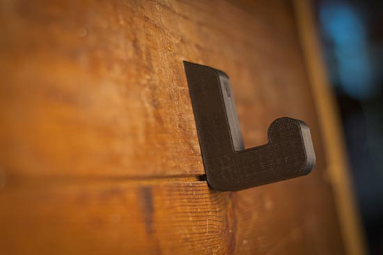
Here’s a few photos of the final printed piece. There’s a few more photos in the DCRL album on Flickr as well.

DCRL Coat Hook

DCRL Coat Hook

DCRL Coat Hook

DCRL Coat Hook

DCRL Coat Hook

Categories
Uncategorized

CheerLight 2012

CheerLCD

Here’s my CheerLight 2012 device, which I call the CheerLCD! And what is CheerLights you say?

CheerLights is an ioBridge Labs project that allows people’s lights all across the world to synchronize, stay linked based on social networking trends. It’s a way to connect physical things with social networking experiences and spread cheer at the same time.

Much like last year, I’ve opted for a small desktop display—a USB-powered computer peripheral—rather than some giant string of multicolored lights…

CheerLCD

With the combined power of 3D printing, affordable electronics, and the duct tape of programming languages that is Perl, we’ve developed a device that informs you of what color the CheerLights around the globe are, not only with color, but with words!

(Though we’ve not yet done extensive testing, the text should be legible even by those suffering from color blindness. Accessibility, FTW!)

CheerLCD

The CheerLCD consists of a USB + Serial Backpack Kit and LCD Display from our friends at Adafruit Industries. But you can’t just have a display without some sort of thingy to display the display properly… enter the 3D Printer!

CheerTree

The CheerTree was designed specifically to hold the LCD Display. I utilized Inkscape for the design of the front plate, and then brought that shape into OpenSCAD to add the base and create an STL file for printing. (It ended up warping a bit but that just adds to the charm and aesthetic of the overall device.)

I know what you’re saying, “This is all well and good… but we need to see the CheerLCD in action!” As you wish, my friends… as you wish.

There’s some code over on github/CheerLCD, and some files on Thingiverse for the CheerTree.

Enjoy the Holiday Cheer!

Categories
Uncategorized

A Maker’s Perspective

Laser-cut wood

I was at Milwaukee Makerspace, using the laser cutter (that I adore so much) and another maker asked me some questions, and then offered their thoughts. This was nothing new, and it’s a welcomed thing. Often you’ll get suggestions or ideas for future projects (or the one you’re currently working on.)

The maker was looking at what I was doing (making a laser-cut spool) and said he would probably use a band saw to cut the wood, and find a large dowel to put in the middle. That’s definitely one way to do it.

He guessed about how much time I spent on my method, and if you count the file-diddling his estimate was probably low, and I’m fine with that.

Testing...

But hey, it’s all about perspective, right? I’m comfortable with software, and I like learning and designing things, so I don’t mind picking up new skills in solid-modeling and file conversions. These are skills I’d like to improve, as I plan to use them again and again. If I was just picking up a piece of wood and going at it with a saw… that’s not very enjoyable to me. I’m also not very good at it.

Spool

So instead of just finding a piece of wood and making it work with a saw, I prefer the process I took. I found something close enough to what I wanted, modified it to be exactly what I wanted (and along the way got help from another maker (Gary) and learned more about OpenSCAD) and after some tweaks I should have a repeatable process that will allow me to make as many spools as I want with relative ease. Since I’ll be sharing my files, it also means that others can make the exact same thing. To me this is powerful stuff, and while dumb power tools have their place, the smart tools (design software + CNC machines) offer so much more.

I’m also contributing to a community of makers who share their work, make derivatives, suggestions, and mashups of their work, and allow anyone else to do the same. I’m into that stuff, so yeah, that’s my perspective.

Categories
Uncategorized

Simplfying STL Files with MeshLab

Cow (Sketchup)

So back when I first used the MakerBot at Milwaukee Makerspace, my daughter asked me to make her a cow. (The kid likes cows!) Since my 3D modeling skills were not up to the task (and still aren’t, at least not for a cow) I found a cow in the Google 3D Warehouse and brought it into Sketchup.

It looked fine, so I exported it as an STL file and did a print. A very small print. It looked OK (but not great) and since it was small there wasn’t really much detail.

Since then I’ve looked at other files in the Google 3D Warehouse, but since most of stuff there is for screen display and not 3D printing, things tend to be very complex, at least in the well done models. More complex than might be needed for a 3D print, at least from the Makerbot.

I’m still pretty new at this 3D modeling stuff, but simplifying the model seems to be what we want. In the 2D world I’ve been doing the same sort of thing for 20 years, but in 3D? It’s new ground.

Enter MeshLab!

From the MeshLab web site: “MeshLab is an open source, portable, and extensible system for the processing and editing of unstructured 3D triangular meshes. The system is aimed to help the processing of the typical not-so-small unstructured models arising in 3D scanning, providing a set of tools for editing, cleaning, healing, inspecting, rendering and converting this kind of meshes.”

I’m mainly interested in using it to reduce the complexity of 3D models.

Cow Original (MeshLab)

Here is the STL file I created from the original cow in Sketchup, as seen in MeshLab.

Cow Reduced (MeshLab)

Here is the same file after reducing the complexity using the Quadratic Edge Collapse Decimation filter. I still feel like it’s a bit of black magic figuring out exactly what numbers to use, and what checkboxes to check, but this is what I used for this one:

MeshLab Settings

I’m fairly pleased with the results (though I haven’t tried to print it yet) but now that I’ve got a (loose) handle on mesh reduction, I’ll dig into the tutorials on YouTube from MrPMeshLabTutorials, including this one on Decimation.

(Of course I still wish MeshLab had an Undo function.)

Oh, and if you really want to 3D print a cow, this recently added to Thingiverse cow is probably the one you want. :)