Categories
Uncategorized

Square Thing, Round Hole

Meter in Mount

What do you do when you have a square thing and want to mount it in something but don’t have the ability to make a square hole? (Okay, I know it’s a rectangle in this case…) Well, you put the square thing in a round thing and then make a round hole.

With some current projects I’ve been thinking a lot about how things can be done using specific tools, or a limited set of tools. For instance, if you’ve got a 2-1/2″ hole saw you can make a round hole and then drop this into place and hold it down with two screws.

Circle

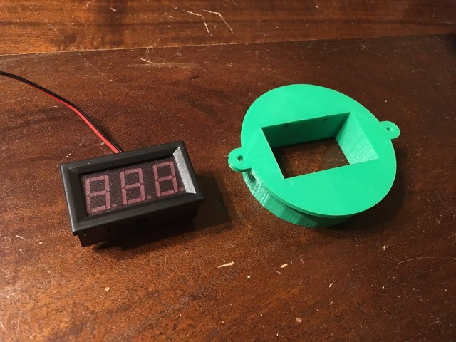
I started to model this mount before I even had the meter. I drew up a rectangle of the dimensions specified on the eBay listing for the item (hoping they were accurate) and I then drew a circle around it to enclose the meter and rounded it up to 2-1/2 inches as that’s a hole saw size you can actually buy.

meter-05

From there modeling the mount in OpenSCAD was pretty simple. It’s about 25 lines of code, and the panel press fits perfectly. I added two ears to put some #4 screws through to hold it down to the panel.

Meter and Mount (Back)

I’m not totally jazzed about the open back. I supposed I could pour a lot of hot glue in there… Actually, at a minimum I may add some hot glue to the wires to act as strain relief so they don’t get pulled loose. (I supposed modeling some sort of strain relief mechanism into the mount would have been a good idea.)

Meter and Mount

And of course while this version is expected to mount (nearly) flush with the panel, I could easily make that mounts on top of the panel and just has a small hole drilled through it for the two wires. So… many… options.

Meter in Mount

Categories
Uncategorized

USB Panel Mount

USB Mount

I designed a small part to hold a panel mount USB cable. I started with the Phoenix Connector Mount I briefly mentioned before, and did some quick modifications to make it work with the USB cable.

USB Mount

I designed this thing in OpenSCAD though I did borrow a few elements from another recent model so that I could use 5/8″ #4 screws. The bottom where the screws go in is set to a height that allows the screws to go in just under 1/4″ which is enough to hold, but not enough to go through the material they’ll be screwed into. This is one of the things I love about making custom mounts and brackets, you can configure them to match the hardware you have available.

USB Mount

With many of the things that need (semi) precise placement of things, it takes two to three revisions to get it right. I actually used the second revision because I was in a hurry, but I’ve modified the file so version 3 will be just right next time. (I had the panel mount screw holes just a little too close together. Things flex enough that it works, but it could be better, and will be… next time.)

USB Mount

The first version actually warped quite a bit in printing. It’s a problem we seem to have occasionally with the old MakerBot. It’s always the front left corner of the print. I find that by shifting the print on the bed to the right just a bit often fixes the problem (at least for small prints.)

USB Mount

You can find this design on YouMagine and Thingiverse.

Categories
Uncategorized

Boom Pole Mount

Boom Pole Mount

Recently I’ve been on a few shoots where I’m doing the audio, and if you’re holding a boom pole and trying to keep the mic out of the shot, it can be a bit difficult to adjust the recorder, which you’ve typically got resting on something nearby, or if you’re moving around, holding in your hand. Obviously I needed a “BPM” and this time it’s not “Beats Per Minute” but “Boom Pole Mount”, which will hold the Zoom on the boom pole freeing up one hand to made adjustments or, you know, help steady the boom pole. (Maybe it needs a better name, like “Zoom2Boom” or something.)

As often is the case… 3D Printing to the rescue!

3D model

I measured the second segment of the boom pole and it came in at 30.2mm in diameter, so I fired up OpenSCAD and started to design a piece that would mount to the pole. (I should also note at this point that I’m not the greatest at math.)

2D test

I thought that instead of printing a test piece I would make a paper prototype to test the fit, so I converted my 3D STL file into a 2D DXF file in OpenSCAD. I figured that wasting a bit of paper was better than wasting a bunch of plastic. It’s also much faster.

Silhouette cutting

I used the Silhouette Cameo to cut my DXF file using a page from an old calendar. (Reuse! Recycle!) Of course once it was cut I realized that I used 30.2mm for the radius instead of 15.125mm. Drat! Lesson learned, you can use d for diameter instead of r for radius in OpenSCAD.

Final 3D model

Back to the old drawing board, by which we mean the “constructive solid geometry” software. This is version 2 of the design. Version 1 was lacking the holes for the hex bolt heads to fit into on the flanges, and was a little thin. Version 2 seems to have resolved all the issues that version 1 fell short on.

Boom Pole Mount

A few bolts, nuts, and knobs (just like the arm uses) and we’ve got a pretty solid piece that I trust to hold the recorder to the boom pole with. The one thing we may need to watch out for is over-tightening the knobs, as that could lead to cracking the plastic. I can probably solve this by adding more infill to the print (it’s at 35% now) or by a slight redesign. We’ll field test this one first though, to see how it holds up.

Categories
Uncategorized

A New Arm (Part II)

Assembled Arm

In my previous new arm post I banged out a quick ‘n dirty replacement arm to hold an LCD display on a RED camera using some 3D printed parts and a few nuts and bolts.

Arm Parts

Version 1 worked, but I wasn’t totally happy with it. Iteration time! The beauty of digital fabrication using a 3D printer is that it’s easy to revise your design and try something new.

Block 1

One of the issues I had with version 1 is that things spun around too much. Even with the tightening bolts, there was more spinning happening when less spinning was desired. I ended up adding a hex-shaped hole to hold the head of the bolt in place. This resulted in less spinning.

Block 2

I then figured that if one hex hole was good, two were better! Sadly, while this worked well for the first corner piece, it didn’t work as well for the second corner piece that was held in place with the nut knob.

Block 3

No problem! OpenSCAD makes it easy to comment out a piece of code and output a new STL file. I now have two (slightly) different versions of the connecting block. Oh, I also rounded the edges a bit, which resulted in a better print, and a better feel.

One thing to note here. Where I originally posted an image of the connector block (before I even printed it) I made a comment about milling it from Aluminum. (Though ultimately it was decided that a drill press and band saw might be all the tools needed.) Milling this new design would probably still be doable, but until I’m sure we like this version, what’s the point? I may end up revising again.

Nut 1

And then there was the knob… The knob I had previously been using was one of the first things I ever printed on my RepRap. I’m sure I grabbed it from Thingiverse, but I’ll be damned if I can find it now. It may have been removed. Nevertheless, I didn’t love it, so I designed a new one. This is version 1, which was ok…

Nut 2

This is version 2, with a nice hull operation to give it a more rounded feel, and (probably) make it a little bit stronger. This is my new 1/4″ nut knob from now on. (Unless I design a new one!)

Parts

So yeah, a few 3D printed parts, some nuts and bolts from the hardware store, and we’re in business.

Assembled Arm

Oh, there’s also a screw in place of a bolt on the main support, because attaching it to the camera will be ten times easier with this feature, and you may also notice a slightly smaller version of the knob on the lowest mount point. This is (probably) needed to allow clearance to tighten it. (I didn’t have the camera around to test with, but I’ll find out this week if it works.)

Update: Tested it, seems to work well! You can grab the files from Thingiverse.

Arm on RED ONE

Categories
Uncategorized

A New Arm (Part I)

I’ve made elbows before, and while I should be making hands, I ended up working on a new arm this weekend. Rather than do all the work and just show the final thing, I thought I would do what I did with the MMPIS and post as I start a project so you can see all the steps involved.

RED ONE

As you can (sort of) see in the photo, the camera has an LCD display that is attached to an adjustable arm. You can even look at it while talking on the phone! The nice thing about the arm is that by twisting just one lever, you can adjust it to any angle, and then lock it down. The terrible thing about the arm.. is, well, everything else.

RED ARM

The arm held up to over 4 years of use (and abuse) but finally failed. Things wear out. It happens. I asked one of my camera rental guys about repairing it and he said “Can’t be done, just toss it.” So… Challenge Accepted!

I basically had the arm fixed, but then something else went wrong. It’s sort of a cascading effect with multiple points of failure. If one part doesn’t work, it affects all the parts, and nothing works. We fabricated a new rod, slightly longer than the original, to compensate for the wear on the original rod, but we had to remove a part to do so, and then that part wouldn’t stay secured when you tightened it. It became a vicious circle of fix it, watch it fall apart. Crap! (I still have one idea for fixing it, thanks to David Bryan. Once parts come in I’ll try that fix as well.)

Since I couldn’t reliably repair the arm in a timely manner, I decided to create a replacement. The nice thing about building camera accessories is that you get a lot of mileage out of existing off-the-shelf hardware like 1/4″ nuts and bolts.

Block

I fired up OpenSCAD and started designing a connector block, with the idea that 1/4″ bolts would be the “arm parts” and the blocks would be the “elbows”. There’s a slot to allow for the block to flex when tightened. I’d also be using those little hex nut knobs I use all the time.

Pieces

Once I had the parts printed, I used an X-ACTO knife to clean things up and trim things down. I also used a 1/4″ drill bit to clean up the holes a bit, and a vise to push the nuts into the knobs. All the metal and plastic bits in the photo probably adds up to less than $7 USD. (And there’s a lot of extra pieces here!)

New Arm

Here’s the assembled arm holding up the LCD display on the camera. It does indeed work, but we’re going to call this ‘version 1’ as there is definitely room for improvement. Still, it’s a much more functional arm than the broken one held together with gaff tape.

New Arm

I started making some notes on what worked, and more importantly, what didn’t work, for the next version. Again, the great thing about 3D printing is that it lets you go from an idea to a finished product very quickly, and then to iterate again very quickly. If I just count my time designing and assembling things (and not the time to print the parts) this is probably less than 90 minutes of work.