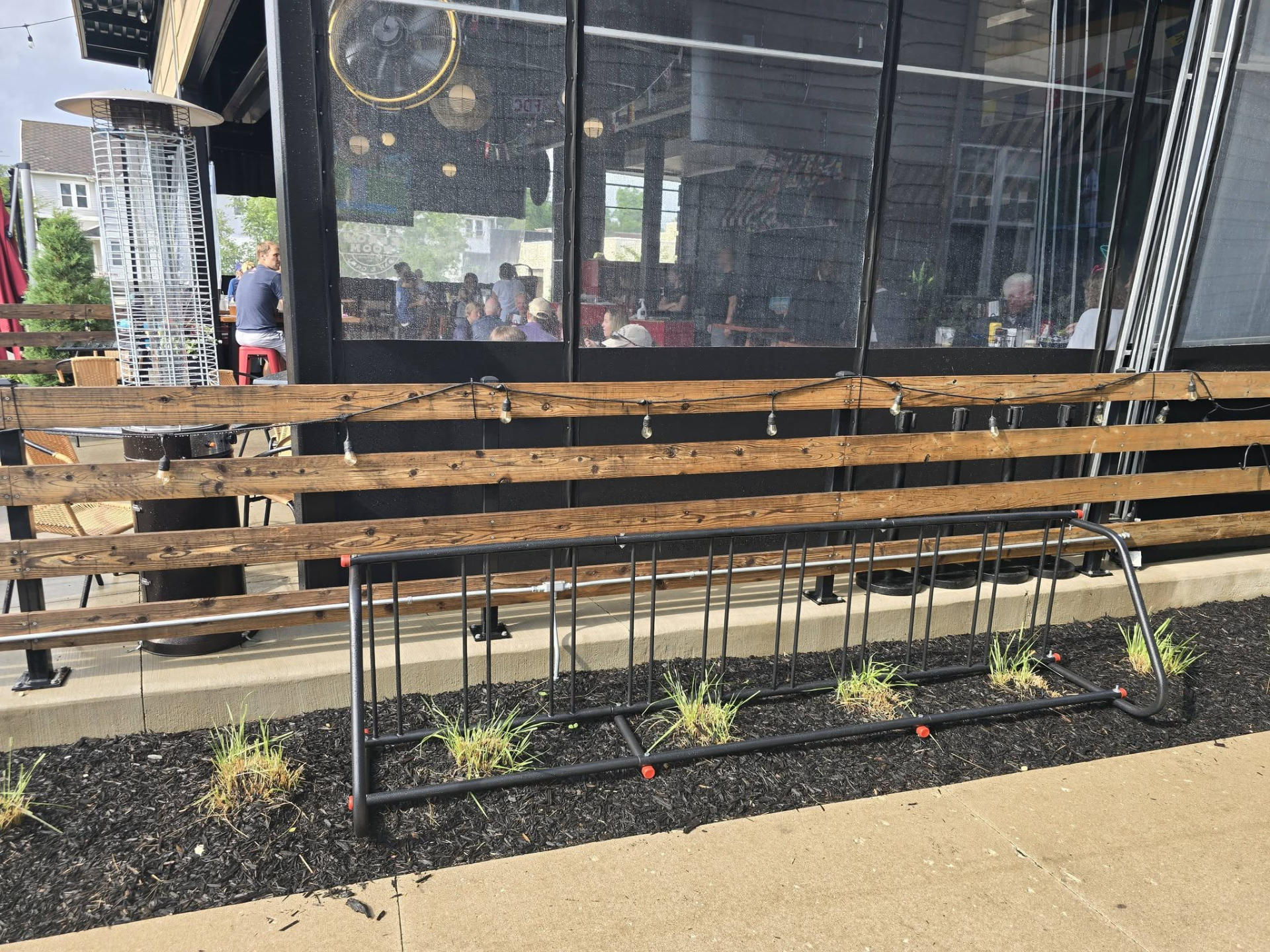
I didn’t mean for this to turn into advocacy. A local business posted about their new bike racks on Facebook. I thought that was awesome! But I had some questions… The first one was, “It it anchored into concrete?” which was based largely on the fact that I often drive to a place and see a 6 foot long bike rack that is not attached and I was able to easily pick it up and carry it around. It’s so insecure I would never lock my bike to it.
I didn’t want to come across as a complainer so I asked a bunch of bike people what their thoughts were, and I’ve distilled them below.
(Note: Some people were very helpful, others seemed upset with me even though I specifically did not name the business in question or try to “call them out”. As I said, I want to collect and gather useful feedback, and I applaud any business that takes cyclists into account.)
Placement
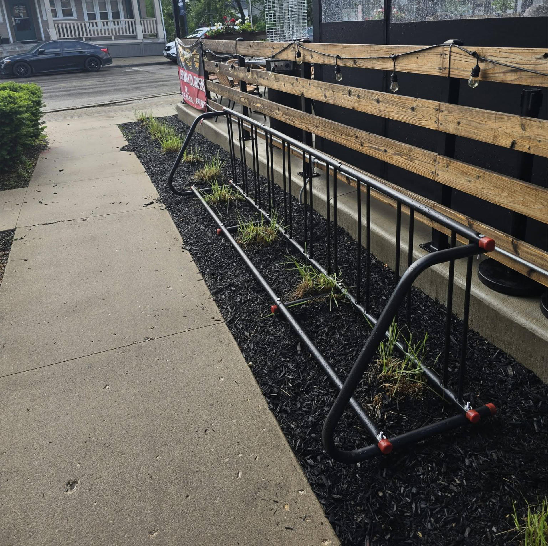
A number of people pointed out that if bikes were placed in this rack they would be blocking the sidewalk. Bikes would be in the way of pedestrians and potentially block wheelchair users from using the sidewalk.
Using bike racks that could be parallel to the sidewalk would allow for bikes to be parallel to the sidewalk, so they don’t take up sidewalk space, or at least a minimal amount of sidewalk space. It may mean fewer bikes could fit, but it could prevent blocking the sidewalk for pedestrians.
Compatibility
Some folks call this type of rack “wheel benders” for a reason. They are meant to roll your front wheel between two bars. If your bike falls over (which is likely) it can bend the front wheel.
This sort of rack also only allows for certain width wheels. Many bikes (ebikes, cargo bikes, fat tire bikes) have wider wheels/tires which might not fit. A few people said they lift their bike and hang the front wheel over the top bar for better security. This is only an option for lighter bikes/people who can lift their bikes that high, though it can allow for better locking the front wheel to the frame around the top bar.
Security
This is a big one. Most people called this style of rack out as insecure. There is no easy way to lock the bike frame and rear wheel to the rack. Some called this a “bike stand” and would never lock up just the front wheel as that can easily be removed and the bike stolen.
Anyone who cares about locking their bike is looking to lock the frame and rear wheel, and this typically means the type of rack you can park next to so a U-lock can be used.
I had concerns about this rack not being bolted down, but people said that no one is going to walk away with a 10 foot rack with a bike attached. I disagree (because I’ve seen crazier shit) but they do have a point. For very casual lockups where you can watch your bike this rack could work, but it’s definitely one of the least secure style of racks.
The upside down U shaped racks bolted into concrete are much preferred. The are more secure, more versatile, and more compatible with more types of bikes… and if placed parallel to the sidewalk would not block the walkway.
Quality
As mentioned, this style of rack is not great. One person told me they could disassemble it with a wrench in their bike bag… once disassembled the bikes are no longer “locked” to anything. And of course the “wheel bender” comment comes to mind. I get why this style was chosen, as it’s probably pretty cheap, and I get it. This sort of rack can be useful for standing up bikes in a secure facility (think bike parking inside a building, at work or an apartment building.)
Okay, so now what?
I’m sharing this post with the business in question. I hope they take no offense. As mentioned, I only want to help. If I were to recommend bike racks I would choose the upside down U style, and anchor them into concrete. And for this specific installation I would run them parallel to the sidewalk so bikes do not block where pedestrians need to go. That’s probably the number one issue with this rack, the placement in relation to the sidewalk.
Got any comments? Please leave them below!