Categories
Uncategorized

Reprogramming an ATtiny85 Blink/Fade Board

A few years ago I helped Josh with the code for the Blink/Fade Board that Brown Dog Gadgets has in their Crazy Circuits kit.

This is a simple board that comes preprogrammed to do a few specific things, with the idea that you can start using it even if you don’t know how to program or upload code to a controller. Besides power in, ground, and reset, there are five GPIO pins that we can use:

  • Pin 0: fades in and out
  • Pin 1: heartbeat
  • Pin 2: twinkles randomly
  • Pin 3: blinks on and off
  • Pin 4: blinks off and on (alternates with Pin 3)

We’ve always said that expert users could reprogram it to do anything an ATtiny85 can do, but we never had a guide… until now. Courtesy of Brown Dog Gadgets here’s the Guide to Reprogramming a Blink/Fade Board!

We’re using the Arduino IDE along with a SparkFun Tiny AVR Programmer to do the heavy lifting… You’ll also need to build a little LEGO jig with some Maker Tape and Crazy Circuits components and some Dupont jumper wires to string it all together.

After I reprogrammed the board I popped it out of the programming jig and popped it into a simple circuit to control the brightness of an LED with a potentiometer. You can’t do too much with an ATtiny85 but it does have a few inputs & outputs and you can even control a NeoPixel strip with it! (A guide for that will be coming soon.)

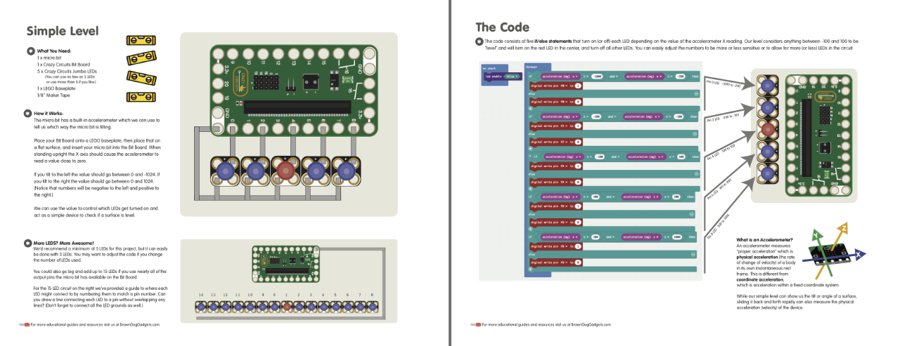
Like most of the guides we do there are some nice diagrams and downloadable PDF files with more/helpful info. Here’s one covering the reprogramming aspect of the guide…

And here’s one that shows using the reprogrammed board in the LED/potentiometer circuit. (The code for BFDimmer is available.)

I’ve been doing my best to keep cranking out fun and educational guides for projects. While a lot of them have been focused on simple circuits or Arduino-based things, we’ll be expanding into Micro:bit projects in the coming weeks, which has definitely been interesting.

Categories
Uncategorized

SparkFun Multimeter Detent Repair

I’ve got two of these SparkFun Multimeters, which is a good basic meter for the price. I’ve had them for years and they’ve worked well… except for one thing. Every now and then the detent fails and the dial still turns fine but doesn’t click into place. It’s a minor annoyance, but life is full of minor annoyances. Since I had to fix it again today I figured I’d write it up so I remember how to do it next time, and others might also find it useful.

There are three screws to remove to open it up. One small one for the battery compartment, and two holding the case together. Get a small Phillips head screwdriver and get to it.

There are four screws holding the circuit board to the front of the enclosure. Sorry, this is the best photo I have. Look for the screws, you’ll find them.

The front half of the enclosure has the dial in it. Lift it out… oh wait!

At this point I should have mentioned that if you hear the tiny metal ball rolling around inside the meter you should carefully open it so you can capture it and it does not roll away. It’s tiny! There’s also a tiny spring you’ll want to find. That’s pretty important.

Oh, look! There they are. Now, there’s a good chance there should be two balls and two springs, but I probably lost a pair long ago. No matter, let’s keep going… If your spring and ball are nowhere to be found, look on the floor.

Okay, there’s a pocket in the front of the enclosure where you place the spring and then the ball. There are two pockets, one on each side of the dial. As mentioned, I only have one spring and ball at this point. Argh…

Yeah! Back in place… carefully put the dial in place, then reassemble in reverse order you took it all apart, and it should be good. Again, this post is mainly for me the next time I need to do this since I stared at the whole thing for five minutes before I remembered how it all goes. Good Luck!

Categories
Uncategorized

Game Boy Camera

I remember seeing people use a Game Boy Camera years ago, and with my interest in lo-fi tech (and probably spurred on by 8bitMKE) I ordered a Game Boy Camera for $11.97 on eBay almost two years ago (Hey, sometimes projects take a while.)

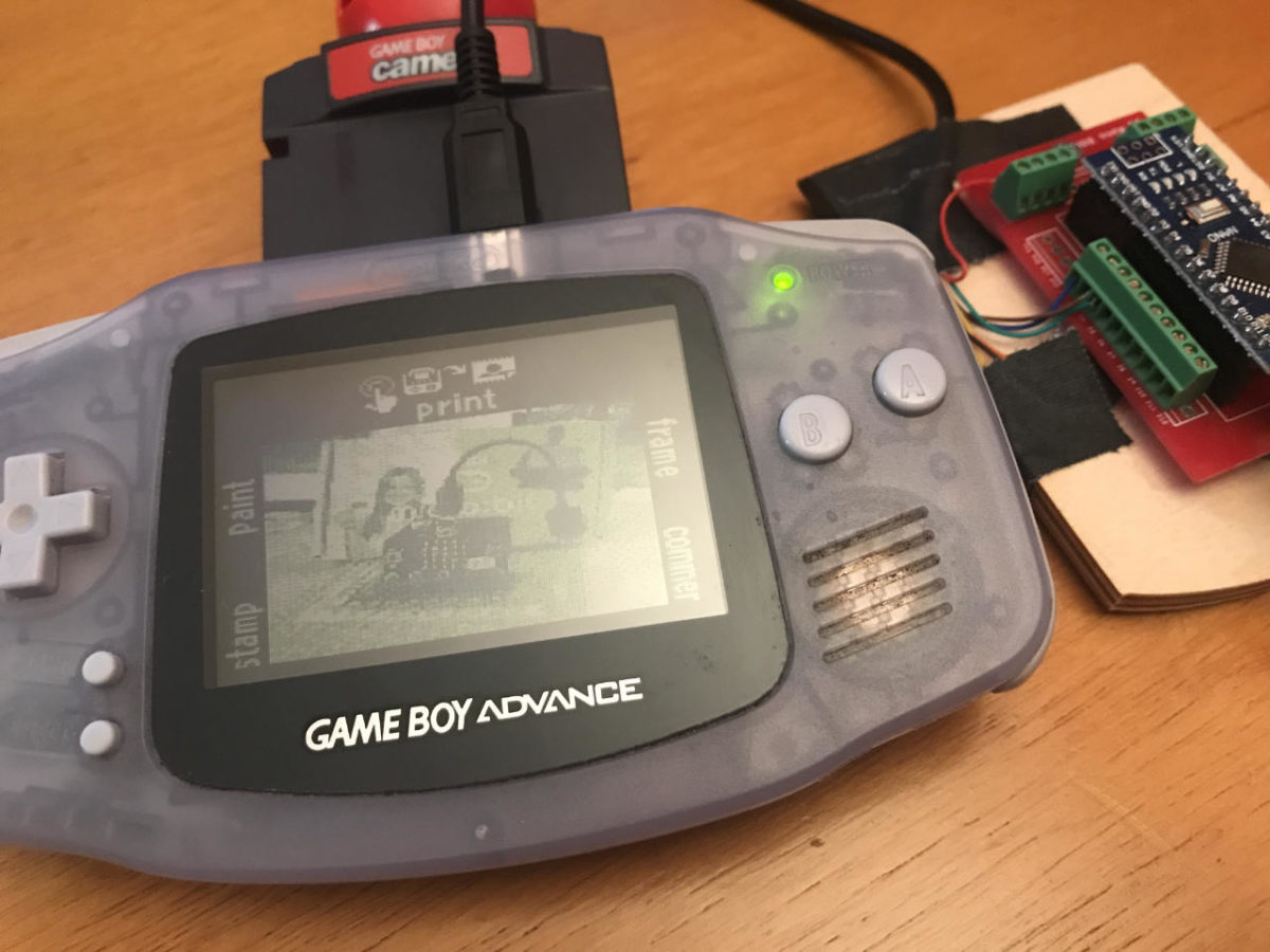
Last fall when my daughter moved out we found her old Game Boy Advance, and after a good five minutes of Tetris I popped the camera into it and took a few photos. But alas, with no way to transfer them out of the Game Boy, they were stuck there…

After some digging around I found some posts that mentioned using an Arduino to transfer the photos from the Game Boy to a computer. Arduino you say? That’s my jam! But even then it took some time before I did anything.

I finally got the cable I needed (a “Two Player Link Cable Cord for Nintendo Game Boy”) for $3.99 on eBay after first ordering the wrong cable, and I quickly grabbed an Arduino Nano, one of my breakout boards that was already soldered up, cut the cable in half, stripped the wires, grabbed a multimeter to figure out which was which, and got it all wired up.

The arduino-gameboy-printer-emulator repo on GitHub proved the most useful to me in getting this all set up.

The process to transfer involves connecting the Game Boy and “printing” the photo you want while the Arduino serial monitor is open and set 115200 baud. The data will flow into the serial monitor window, then you copy it and paste it into the decoder and you get your image.

While I’ve got a DSLR, a phone, a Raspberry Pi camera, and other ways to capture images, the Game Boy Camera is definitely one of the more esoteric methods of doing so. Stay tuned to see what I actually do with it.

Categories
Uncategorized

Manual Crankable Larson Scanner

The most recent fun project at Brown Dog Gadgets is our take on the classic Larson Scanner. EMSL has an awesome kit, and many people who have experimented with an Arduino and LEDs have made a breadboard version.

Well, Josh and I made a LEGO version using Crazy Circuits parts, and instead of a microncontroller it’s controlled by a hand crank! Yeah, it’s an Analog, Hand-Cranked, LEGO-Based, Crazy Circuits Larson Scanner.

As with all of our projects, the instructions, files, templates and all that are available for free. Check it out! You can certainly use other components besides Crazy Circuits and Maker Tape for this, but as always, getting parts from us (or a reseller) ensures we can keep producing open source educational content and curriculum. And yes, schools, teachers, maker clubs, and other use these resources, and we incorporate their feedback into new designs and projects.

There’s a bit of an explanation about the cylinder and “coding” as it were, in the instructions. While this is a simple & fun project, you can expand upon the basic concept to talk about more advanced concepts. That’s pretty much our goal with these things.

Josh had a lot of fun making the video for this one, though I’ve heard that stock music way too many times in other videos! ;)

Perfect for your Knight Industries Two Thousand or Cylon!

Categories
Uncategorized

Crank Activated LEGO Circuits

The latest project for Brown Dog Gadgets is a LEGO-based, crank-activated circuit. This is a simple build that uses LEGO along with Maker Tape to allow a rotating cylinder to close a circuit.

The trick here is that Maker Tape is not just conductive, but it’s strong, and can be stretched just a bit against the cylinder to provide good electrical contact. Besides a few LEGO bricks on a baseplate we’ve got some round LEGO pieces for the cylinder, two bricks with holes, a long and short axle, and a beam with axle holes to make the handle. Overall, pretty simple.

This is one of those projects which really highlights what Maker Tape can do. There really isn’t an easy or reliable way to do this with wire, or with copper foil tape.

The video below shows the circuit in action, and if you want more, we also showed it off during one of our live video streams that we do each week.

As always, get the full details of this build on the Brown Dog Gadgets Project Site. And yes, we’ve got a lot more fun coming with crank activated circuits!