Categories
Uncategorized

S1 Rotary USB Controller

You may already know that I’ve been building (and selling) USB controllers for the last 9 years or so. Most of them have been for photobooths, tradeshows, exhibits, museums, etc. Well, the pandemic blew things up, in a bad way, with no events happening, so I’ve tried to keep going, and occasionally do custom development, and then turn custom things into products, so here’s the S1 Controller.

It consists of a rotary encoder, meaning it can turn forever in either direction, with a built-in button. Just like the scroll wheel on your mouse! So, what can it do? Well, what do you want it to do? The first one I built was for an audio nerd who didn’t like spinning the scroll wheel on his mouse and then clicking the left mouse button to set the dials in their audio software, so this gives a real-world analog to turning knobs and setting values. I can appreciate that!

It could also be programmed as a volume control and play/pause button, or some other custom thing. I never really know what people will come up with, but 99% of the time I can program what they want. Maybe you want one of these? If you do, you can grab one from Etsy. (Update! Lots of people have wanted these for MIDI related applications, and that works too. If you need a special MIDI controller, we can do that.)

Update: There are now two new versions: S1D Controller and S1A Controller.

Categories
Uncategorized

Omni Wheel Robot (LEGO Build)

I’ve always found omni wheel robots fascinating. I even tried to design my own omni wheel (which did not turn out great.) But over at Brown Dog Gadgets I thought we should give it a try and build an Omni Wheel Robot. (And there’s a full guide and code available.)

This is a perfect use of LEGO parts. It is completely possible to fabricate all the parts needed to build this, either using digital fabrication (laser cutter, 3D printer, etc.) or by hand, if you’re the handy kind. But honestly, the LEGO aspect made the build super-simple, and the guide links to all the parts on BrickOwl (which are all pretty cheap.)

The other magic of this build is using 4 servos instead of stepper motors. While you do lose precision, this makes things much less complex and just simplifies everything. We’ve also got an Arduino and a battery pack. That’s it. Yeah, the goal was simplicity.

This is a beginner project in many ways, but it can also serve as a platform for code exploration. We provided the basic code for movement, but there’s room to expand on that, add sensors, etc.

And since it’s LEGO, it is by definition a platform you can build upon and add to. (We’ve even got 3D printed LEGO compatible parts for you.)

Check out the guide to this Omni Wheel Robot if you want to learn more.

Categories
Uncategorized

Fun with WS2812 LED Sticks

Back when I used to build museum exhibits we put WS2812 LEDs (also known as “NeoPixels”) into things. Lots of things. Sometimes inside cabinet walls or tubes or pipes for glow effects, and sometimes as feedback devices for interactivity. I’ve also built a few signs before, so I’m not new to NeoPixels/WS2812 LEDs…

But I never seem to have any laying around wired up to just mess around with. So I fixed that. I mean, I’ve got tons of strips lying around in a box in my office, but I wanted something smaller and easier to deal with. I found these poorly named Comidox 5PCS WS2812 5050 RGB 8 LEDs Light Strip Driver Board 8 Channel Built-in Full Color-Driven Development Board Black for Arduino which is 5 sticks with each having 8 LEDs, for a total of 40 NeoPixels. (And yeah, it was less than $8 for 5 sticks! That’s 20 cents per NeoPixel.)

What I didn’t know when ordering is that they came all together as one that you are meant to snap apart. Why bother!?! I just soldered them up to make an LED matrix! (Terrible soldering, but it does work.)

Now I feel like I have something handy, on my desk, that I can easily use to prototype NeoPixel development. I started out with the Adafruit_NeoPixel which I’ve used in the past, but now I’m using the FastLED library, which so far seems pretty awesome. There are also some matrix libraries I’ll need to investigate. I’m running these from an Arduino Pro Micro with the Leonardo firmware on it, which seems totally up to the task.

By the way… I recently realized it’s been over 10 years of “screwing around” with Arduino boards, and in that time I’ve been a Technical Editor for two Arduino books, taught Physical Computing (“Arduino for Artists”) in a university, taught classes at a makerspace and a museum, and written plenty of guides about Arduino projects. It’s been an interesting ride!

Categories
Uncategorized

Garage Fix (Again 2!)

I’ve got a new garage door fix. Again. I forgot to explain the last fix, which sort of worked, well… worked fine for years I guess, but now it doesn’t. Oh, start at Garage Fix (At Last!) if you want the back story… The short version is, with a combination of sunlight, snow, and a specific time of day, the garage door will not close due to the electric eye being affected by light from outside the garage.

After the first repair (mentioned in the blog post linked above) it didn’t quite do it so I ended up moving the electric eye sensors to the top of the garage. The illustration above is a view from inside the garage looking out, with the door open. The red sensors are the old location, and the green sensors are where I moved them to. I also ended up making a flag below the sensor because this solution also did not always work. Arrrgghhhh. Oh, I should mention that the sensors where they are will never detect a child running under the door, but the alley kids are all six years older now, so they should know better. ;p

So these fixes worked pretty well (for years actually) until last week, so on to another.

I realized that if you pressed the garage door button (which I replaced years ago with a green arcade button) the door would start to close, then when light bounced off the door and hit the sensor it would stop and reopen. I also realized that if I pressed and held the button, it would close!

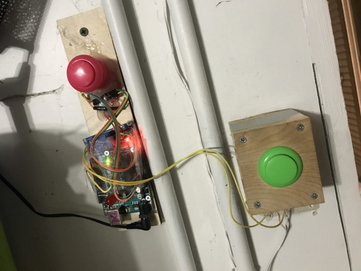
Well that’s easy! All we need is a way to press and hold the button for as long as it takes to close the door. While it was -0 degrees out I prepared an Arduino and a relay, a pink arcade button, a chunk of wood, found a 12 volt power supply, and hot glued it all together. I wrote some code that would close the relay 5 seconds after the button was pressed and then open the relay 30 seconds later.

So here’s what happens now. When I leave in the morning I pull out of the garage and use my remote to close the door. If it does not close I get out of my car, go into the garage, press the pink button, and then walk briskly out of the garage before the door closes and crushes me. The door closes as I get in my car, and we’re all good.

This is one of the ugliest builds I’ve done it a while! As mentioned, I literally threw this together as quickly as possible. I did not design anything, did not build an enclosure, didn’t make labels… nothing. I drilled a hole in the wood and screwed it into the drywall and wired it in parallel with the existing button which usually works to close the door.

So now it’s, press the green button to open and close the door, and press the pink one if the green one doesn’t work. If you drive out of the garage and your remote won’t close the door, get out and use the pink button. Yup. Sigh.

Obviously the next step is to design an enclosure, add proper labels, rewrite the code, add status and indicator lights, probably a 7 segment display with a countdown… and then hey, might as well use an ESP32 so I can add remote control via WiFi. Oh, I should probably also add a sensor to check if the door is opened or closed. And also a status web page I can then check with a service running locally on the network, tied into Pushover to send me alerts. Ah, plus a real time clock module so I know when things happen in case I need to correlate times with the security camera.

I expect to have the new version done within 18 to 24 months.

Categories
Uncategorized

The LED Burns Bright

Disclaimer: I have destroyed light emitting diodes (LEDs) in the past. Typically on purpose, by feeding them too much voltage until they burn out in a bright flash. It’s fun to do if you’ve got a variable power supply with a dial and can slowing crank up the voltage.

That said, this is about trying to destroy an LED without trying to destroy and LED. (Or maybe, trying to not destroy an LED but still breaking the rules.)

The rules you say? Yes. As in, you need a resistor when connecting an LED to an Arduino. This is just, like, a fact. You can get away with putting a resistor-less LED on an Arduino for testing, or learning, or a quick demo, but to do it right, always add an appropriate resistor inline.

There’s a web site called LEDCalc.com that helps you determine the appropriate resistor for the LED and voltage you are using. Tell it you’ve got 5 volts, one LED with a voltage drop of 2.0 volts, and want to give it 20 milliamps and it will tell you to use a 180 ohm resistor. (There’s fancy maths to figure this out as well, but I’m an artist who does not excel in maths.)

In the photo above you’ll see a (very bright) yellow LED connected to an Arduino Nano. (This Nano specifically is manufactured by Elegoo.) I have no resistor in my circuit, I have nothing else connected, just a single LED on a single pin, with a digital write to turn it on at full power. (As it were.)

Okay, so at some point the LED will be destroyed, or the pin on the Arduino will be destroyed, or the Arduino itself will be destroyed, or some component will fail. But… when will that happen? I’m a week into this experiment, and so far, all is well. Will it take a month, a year, a decade? Is the time to failure completely unknown, and completely random. Is it pure luck that this works, and it could fail any second now? Do I need to blink it on and off to get an inrush of current to the LED to stress it more?

I found this Arduino MEGA with 27 LEDs connected to 27 different pins, which I used for testing, and it seems fine as well. Granted, I don’t have all LEDs on at the same time for any real length of time. It’s a blinkenlights thing so lots of off time and some on time.

I’m now really tempted to change the code so it just turns on all 27 LEDs at once for an extended amount of time. I’m a bit curious about this whole thing now. I understand the reasoning behind current limiting resistors, but I’m wondering how that comes into play in the real world. One of the trickiest things I’ve dealt with when designing circuits is that they should work, they work on paper (or on the screen) but in the real world something goes wrong. EMF, physics, gremlins… whatever. Something you don’t expect comes along and screws things up… But this seems like the opposite, where we plan for what should/could go wrong, but then it doesn’t.

I probably need an actual Electrical Engineer to walk me through this one…