Categories
Uncategorized

Fritzing + OSH Park = PCB!

Teensy BOB v1.0

I recently created my first “real” printed circuit board. By “real” I mean one that I sent out to get fabricated, not one I did at home by etching it myself. The board is for a Teensy LC, and breaks out most of the pins to screw terminals. (Pictured above is version 1.0, which has been revised due to a few spacing issues and the mounting holes being too small. You can see I had to drill them a bit larger.)

Teensy Proto

The Teensy LC BOB (BreakOut Board) came about due to my use of the Teensy for a few museum projects that were using the controller as an input device for a computer. I had been putting the boards onto Adafruit Perma-Proto Breadboards which are great to work with, but after building a few of these that were very similar to each other, I thought I could just design my own PCB to get the job done. (The board I designed probably cost about $2.15 more than the Adafruit boards, but it’s also designed to be exactly what I need.)

Breadboard in Fritzing

I started by designing what I needed in Fritzing using the breadboard view. I added in the screw terminals I wanted, and wired it all up. At this point spacing doesn’t matter too much, as it’s just to get all the components and connections in place.

PCB in Fritzing

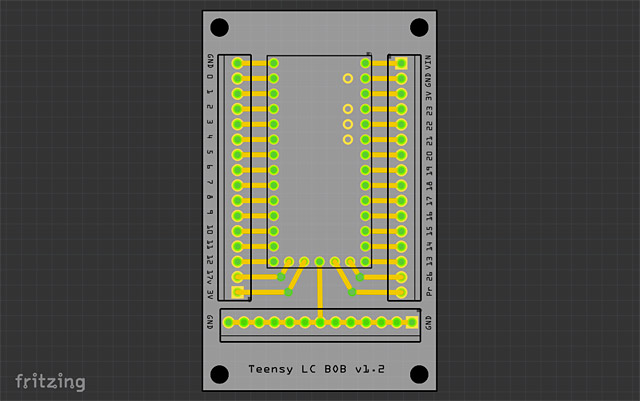
Once all the pieces are in place and connected up I switched to PCB view where you get to see what the actual printed circuit board will look like. Here the positioning and spacing is just like the real world. This step probably tool the most amount of time, and I found the tools a bit lacking compared to something like Inkscape or Illustrator for precise positioning. Part of this could be due to my still learning how it all works. There’s some good info here on designing PCBs in Fritzing. (Eventually I’d like to do custom shapes.)

Export Gerber

After I was happy with the PCB layout I exported it using Export > for Production > Extended Gerber (RS-274X) from the file menu.

Gerber Files

It will output a whole bunch of files to the folder specified. Once I had this folder I made a ZIP file from it, and named it Teensy-BOB.zip and uploaded it to OSH Park.

OSH Park

OSH Park’s web site will check your files and show you previews during the upload process. (Hopefully you can figure out what you’re looking at!) As I mentioned, the first version had a few issues, so I corrected those and put in a new order. For the new version I added the name of the board and the version number. Once I get these back and test them I’ll share the project so anyone can order some if needed. (At least one person at Milwaukee Makerspace was interested.)

I should note that the Teensy 3.x board could also be put on one of these, though the pin labeling is a little different. I’ll probably create another version that is specific to the Teensy 3.x for a future project I’m doing for Maker Faire Milwaukee this year.

Update: OSH Park has some docs on using Fritzing.

Update: Download the TeensyBOB Fritzing file!

Categories
Uncategorized

Here comes the PCOMP!

LED PWM

Somehow the folks at UWM’s Peck School of the Arts convinced me to become an Adjunct Lecturer and teach a Physical Computing course titled “Electronics and Sculpture”. Okay, I’m being a coy, I jumped at the chance, and I’m pretty excited about it!

I’ve been playing around working with Arduino microcontrollers for a little over five years now, building all sorts of strange projects, and truth be told, I did a lot of weird electronics projects when I was a kid, and even took electronics classes in high school. As for the sculpture part, I think a bunch of these projects qualify as sculptures.

Potentiometer LED

I’m still designing the course as I go, so this semester is extra hard. (I taught a digital art lab class last semester, but the material was all provided for me.) Developing curriculum is hard! Luckily I’ve got a great group of students are we’re figuring it all out together. I’m also trying to bring in bits and pieces from the world I’m used to; un-conferences, open-source, hackerspaces, maker culture, DIY, etc. So far it seems to be working.

Photocell LED

As for these diagrams, I did them all with Fritzing. I also recently used Fritzing to design and fab a circuit board. Since it’s proven so useful to me, and using it has somehow become part of my job(s) I wanted to contribute. I donated some euros to the project. I wish I could do more, but perhaps in the future I can contribute more than just cash. Still, it’s a start!

Categories
Uncategorized

Fritzing – Breadboard Illustrations

Fritzing is an open-source initiative to support designers, artists, researchers and hobbyists to work creatively with interactive electronics…

Since I’m a n00b who can’t read schematics, the breadboard view is good for me… Lady Ada uses it in some of her tutorials.

So if you’re just getting into Arduino hacking and can’t read/write schematics, give Fritzing a try… you may get something like this:

breadboard

Here’s my first attempt at a breadboard illustration. This is for a sketch that reads data from the photocell, and lights up the LED if it’s too dark in the room. Oh, and if it’s too bright in the room, it makes the piezo buzz. Pretty darn simple. I’m not 100% pleased with my illustration, but it was my first time, and since I’ve built this more than once, I guess it should be considered a success.

The Fritzing site has a list of projects and the application (and web site) encourage you to share your creations (under a Creative Commons license even!)

Oh yeah, as for calling myself a n00b, I took a number of electronics classes when I was in school (which was a long, long time ago) but I’m finally getting back into this stuff, and it’s exciting. More updates to come!