Categories
Uncategorized

Presentation Camera

Samsung Presenter

When I teach at UWM we’ve got this presentation camera at the front desk that can be used to show the Arduino and a breadboard and how things are connected. I believe it’s a Samsung SDP-860. It was probably awesome in its day, but the quality is not amazing. It does have a number of controls to zoom in and adjust the brightness, and has a built-in light and multiple outputs, but I still am not impressed with the image quality. When I did use it, I just connected it via USB to my MacBook and used QuickTime Player to get a video window and then showed that with the projector. It allowed students to see the tiny components I was using… so yeah, it worked.

But then I thought to myself, “Why not just use a webcam!?” and that’s what I’m going to do. Since I’m not teaching in the Spring semester I offered to do a Beginner Arduino Class at Milwaukee Makerspace, so I built my own camera thing… the Raster Presenter!

Raster Presenter

Yes, it’s basically a desktop microphone stand. There’s a long gooseneck to allow positioning the camera to point directly down at the desk. (It’s similar to the gooseneck rig used on Time Lapse Bot III.) I’m using a Logitech C910, which I’ve had for years, and which outputs some decent quality video.

Raster Presenter

The Raster Presenter is not quite as pretty as the Samsung model, but I dare say the quality is better, and it may even be more adjustable. It’s also lighter, can be disassembled, and does not require an external power supply. (Just a single USB connection!)

Raster Presenter

The camera mounts to a small piece of wood using zip ties that fit into notches. The wood slides into half of a mic holder that came with the mic stand. There’s a little bit of gaff tape to stop it from rotating on the gooseneck, and Bob’s your uncle!

QuickTime

When you launch QuickTime Player you just choose “File” and then “New Movie Recording” and you should see some live video. If it shows the computer’s built-in camera you can change it via the drop down menu.

QuickTime

After choosing the proper camera you can also choose to change the quality. I found that “Maximum” gave much better results than “High”, although it did seem to enable the auto-focus in the camera, which can occasionally be an issue (at least with other webcams I’ve used.)

QuickTime

Once you have all your settings you can move your mouse off the window and the controls (and title bar) should disappear. As long as you’re connected to a projector your students are ready to see the small things you want to show them! In the sample shot above the only light I used was daylight from the window to my left. I could see a bit of static in the image, but even in low-light it looked pretty good. I’ll do some testing to see if I can get away with existing light or need to augment it with another light source.

Categories
Uncategorized

RED Matte Box Rail Mount

RED Rail Mount

NOTE: Want to purchase one?
See our shop for a RED Matte Box Rail Mount

You may remember the Matte Box Flags that I laser cut a while back, or the more recent LCD Arm that I 3D printed, well, there’s another accessory done now, and it took months and months to get it done. (Well, most of those months were due to procrastin—I mean, working on other projects.)

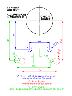
So our story begins with the RED Matte Box, which fits fine on the RED Lens, but when you slap a Zeiss Super Speed in place, the Matte Box can’t attach to it, no worries, RED sells two parts to solve your problem.

Rod Support

Universal Mount

Just drop $350 USD on two parts and you can now secure your matte box to the 19mm rods. This is an ideal solution, but as you know, I’m cheap, and I’m DIY, so away we go!

RED ONE

Here’s how it looks underneath. Those two piece attach together and let the matte box ride the rails, and there’s some latitude for adjusting the height of things. It’s nice hardware, for sure.

RED Mount

Once again I commend RED on publishing nice photos of their products…

RED Mount

…because it’s fairly easy to clean these up and trace them and create 2D profiles that can be extruded to 2.5D designs.

RED Mount

That’s much better! In fact, since it’s 2D I actually laser cut some wood to do a test fitting, since my 3D Printer was down for a bit when I was working on this.

Laser cut prototype

(It was a nice diversion, and honestly I just really like laser cutting things.)

Somewhere along the way though, I pretty much abandoned the idea of recreating the stuff RED has and figured I should just design my own. Maybe after the whole RED Arm debacle I realized their designs are sometimes lacking…

Anyway, I was overly complicating things, so I decided to go simple. Also, we’re 3D Printing here!

Rod Standards

Also, if making any rod-related things, I highly recommend you grab the Rod Standard Graph PDF from the OConor site.

RAIL Mount STL

This is what I eventually came up with. It’s mostly an extruded shape, but it does have some holes for the bolts including bits to lock in the hex heads, just like the Arm does. I wish I could say I just 3D printed this and that was it, but it’s far from it.

While I was working on this I was also working on calibrating the RepRap after the recent repairs, so I had a bunch of issues with things not printing as well as they should, or not exactly the right size, you know, like a 19mm hole printing at 18.673mm or 21.298mm. So I moved back to a bit of prototyping.

RAIL Mount DXF

I used the old STL to DXF trick (thought slightly modified) to create a 2D design from the original 3D file. Once I had a DXF file I could use the Silhouette Cameo to easily cut some thick paper to get an idea of size and dimensions. Eventually I was happy with how things were looking so I moved on to plastic.

RAIL Mount Small STL

Here’s the DXF file extruded to 5mm tall, with the idea being that I could print this much more quickly (and with less plastic!) that doing the full print which is 25mm tall. This worked well, and I was able to test fit it on the rods, but I was still having a few weird issues with the 19mm hole sizing.

RAIL Mount Part STL

I ended up pulling my 5mm STL file into OpenSCAD and doing a difference to subtract most of it and just leave a portion so I could print this and test the hole sizing even faster. This too worked quite well.

This all might seem like a crapload of work to get what I wanted, but there was much exploring and learning along the way, and believe it or not, that’s most of the fun in doing it for me. If I just downloaded and printed something, well, that’s good if you want a thing, but not as good if you want to learn the process of creating a thing.

RED Rail Mount

The final piece, with two 1/4″ hex bolts, some nut knobs (as seen previously), and two smaller screws and wing nuts to hold the matte box in place. There was a little bit of delamination in this print. I may try it on the LulzBot TAZ 3 that we just got in at Milwaukee Makerspace, as I think it will be a good test.

RAIL Mount

Hey, it works! It fits on the rods and holds the matte box in place. Simple enough, right?

RED Rail Mount

railmount15205

Categories
Uncategorized

A New Arm (Part II)

Assembled Arm

In my previous new arm post I banged out a quick ‘n dirty replacement arm to hold an LCD display on a RED camera using some 3D printed parts and a few nuts and bolts.

Arm Parts

Version 1 worked, but I wasn’t totally happy with it. Iteration time! The beauty of digital fabrication using a 3D printer is that it’s easy to revise your design and try something new.

Block 1

One of the issues I had with version 1 is that things spun around too much. Even with the tightening bolts, there was more spinning happening when less spinning was desired. I ended up adding a hex-shaped hole to hold the head of the bolt in place. This resulted in less spinning.

Block 2

I then figured that if one hex hole was good, two were better! Sadly, while this worked well for the first corner piece, it didn’t work as well for the second corner piece that was held in place with the nut knob.

Block 3

No problem! OpenSCAD makes it easy to comment out a piece of code and output a new STL file. I now have two (slightly) different versions of the connecting block. Oh, I also rounded the edges a bit, which resulted in a better print, and a better feel.

One thing to note here. Where I originally posted an image of the connector block (before I even printed it) I made a comment about milling it from Aluminum. (Though ultimately it was decided that a drill press and band saw might be all the tools needed.) Milling this new design would probably still be doable, but until I’m sure we like this version, what’s the point? I may end up revising again.

Nut 1

And then there was the knob… The knob I had previously been using was one of the first things I ever printed on my RepRap. I’m sure I grabbed it from Thingiverse, but I’ll be damned if I can find it now. It may have been removed. Nevertheless, I didn’t love it, so I designed a new one. This is version 1, which was ok…

Nut 2

This is version 2, with a nice hull operation to give it a more rounded feel, and (probably) make it a little bit stronger. This is my new 1/4″ nut knob from now on. (Unless I design a new one!)

Parts

So yeah, a few 3D printed parts, some nuts and bolts from the hardware store, and we’re in business.

Assembled Arm

Oh, there’s also a screw in place of a bolt on the main support, because attaching it to the camera will be ten times easier with this feature, and you may also notice a slightly smaller version of the knob on the lowest mount point. This is (probably) needed to allow clearance to tighten it. (I didn’t have the camera around to test with, but I’ll find out this week if it works.)

Update: Tested it, seems to work well! You can grab the files from Thingiverse.

Arm on RED ONE

Categories
Uncategorized

A New Arm (Part I)

I’ve made elbows before, and while I should be making hands, I ended up working on a new arm this weekend. Rather than do all the work and just show the final thing, I thought I would do what I did with the MMPIS and post as I start a project so you can see all the steps involved.

RED ONE

As you can (sort of) see in the photo, the camera has an LCD display that is attached to an adjustable arm. You can even look at it while talking on the phone! The nice thing about the arm is that by twisting just one lever, you can adjust it to any angle, and then lock it down. The terrible thing about the arm.. is, well, everything else.

RED ARM

The arm held up to over 4 years of use (and abuse) but finally failed. Things wear out. It happens. I asked one of my camera rental guys about repairing it and he said “Can’t be done, just toss it.” So… Challenge Accepted!

I basically had the arm fixed, but then something else went wrong. It’s sort of a cascading effect with multiple points of failure. If one part doesn’t work, it affects all the parts, and nothing works. We fabricated a new rod, slightly longer than the original, to compensate for the wear on the original rod, but we had to remove a part to do so, and then that part wouldn’t stay secured when you tightened it. It became a vicious circle of fix it, watch it fall apart. Crap! (I still have one idea for fixing it, thanks to David Bryan. Once parts come in I’ll try that fix as well.)

Since I couldn’t reliably repair the arm in a timely manner, I decided to create a replacement. The nice thing about building camera accessories is that you get a lot of mileage out of existing off-the-shelf hardware like 1/4″ nuts and bolts.

Block

I fired up OpenSCAD and started designing a connector block, with the idea that 1/4″ bolts would be the “arm parts” and the blocks would be the “elbows”. There’s a slot to allow for the block to flex when tightened. I’d also be using those little hex nut knobs I use all the time.

Pieces

Once I had the parts printed, I used an X-ACTO knife to clean things up and trim things down. I also used a 1/4″ drill bit to clean up the holes a bit, and a vise to push the nuts into the knobs. All the metal and plastic bits in the photo probably adds up to less than $7 USD. (And there’s a lot of extra pieces here!)

New Arm

Here’s the assembled arm holding up the LCD display on the camera. It does indeed work, but we’re going to call this ‘version 1’ as there is definitely room for improvement. Still, it’s a much more functional arm than the broken one held together with gaff tape.

New Arm

I started making some notes on what worked, and more importantly, what didn’t work, for the next version. Again, the great thing about 3D printing is that it lets you go from an idea to a finished product very quickly, and then to iterate again very quickly. If I just count my time designing and assembling things (and not the time to print the parts) this is probably less than 90 minutes of work.

Categories
Uncategorized

Red Flag

We’ve been using the RED ONE a lot in the past few months over at z2 and while we’ve had the matte box for a year now, we never managed to get top or bottom flags for it, so I finally got around to solving that problem.

RED Flag

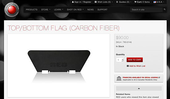
Camera accessories are notoriously expensive. For some things, that makes sense, and for others, I’m not sure it does. The top/bottom flag for a RED Matte Box is $90 USD. Well, hey, it’s carbon fiber. Yeah, that stuff is pricey! But, don’t worry…

RED Flag

There’s an aluminum version of the top/bottom flag for just $40USD. Hey, you could get two of the aluminum flags for less than the price of one carbon fiber flag!

RED Flag

While I was perusing the RED store, admiring their well done photography, I noticed that the large version of the photo was clean. Really clean, and at the perfect angle, straight on! So… I engaged in what I now like to call “R3Dverse Engineering”. (That’s “reverse engineering” of RED stuff, if that was too subtle.)

RED Flag

I grabbed the image from the web site, opened it in Photoshop, and started to clean it up.

RED Flag

I got rid of the shadow, added a white layer below so I could see things a bit better, and selected the object…

RED Flag

I then filled the whole thing with black so I had a high contrast image…

Once this was done, I saved the file as a PNG and imported it into Inkscape, where I used the ‘Trace Bitmap’ feature to create vector lines defining the image.

Inkscape Flag

The next step involved a lot of precise measurements with the digital calipers on the part of the matte box where the flag mounts. There were many guide lines added.

Inkscape Flag

The lines helped me determine centering of the slots and how wide the slots/tabs needed to be.

Inkscape Flag

I did a few revisions, and here’s the final cleaned up version. with most of the guide lines removed.

Inkscape Flag

Here’s a visual diff to show the tweaks between the original trace of the image I imported, and how much I ended up adjusting the lines a bit for a better fit. (The reddish hue shows the final. I mainly had to add a bit more space around the larger tab.)

I should mention that with each revision, I was printing out a sample on tabloid size paper and cutting it up to test the fit.

Inkscape Flag

Once my paper prototype was good enough to consider “final”, I ended up sitting on this project for a bit trying to determine what material to use, and how to cut it.

I’m still thinking about it… I’d prefer to go CNC versus trying to cut it by hand. Perhaps using the CNC Router at Milwaukee Makerspace would work. A very thin sheet of aluminum perhaps? I thought about laser cutting something, but didn’t think acrylic or wood would be a good option. I’ll need to keep thinking about materials…

Black Flag

Meanwhile, we have lots of black board at work, so I stuck my paper prototype onto a piece and hand cut it with an X-ACTO blade. (I did not round the corners.)

Black Flag

The tabs and slots are a little messier than I’d like, but again, I’ll call this part of the prototyping stage.

Black Flag

But it also totally works… and is probably less than 1/100 the cost of the carbon fiber version. It may not hold up as long, but then again, I can easily make a bunch of these for next to nothing. (I can also just laser cut the black board instead of sliding an X-ACTO around to do it.)

Black Flag

Update! I ended up laser cutting the black boards, and they works great!   You can grab the files from Thingiverse.