Categories
Uncategorized

Learn to Solder Kit (Part V)

PCBs

I’m almost set for the Zoom Milwaukee Symposium this week. I’ll be in the Maker Plaza teaching people how to solder with the DIY kit I’ve been working on for the last few weeks. (Check out Part I, Part II, Part III, and Part IV if you haven’t seen them yet.)

PCBs

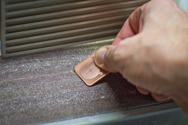
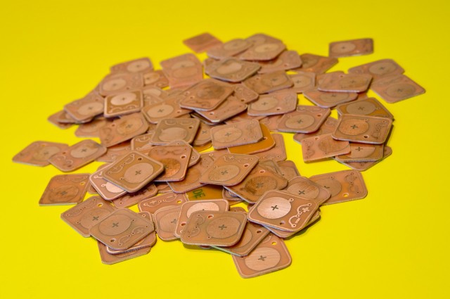
It doesn’t look like a lot, but there’s over 100 PCBs that were made at home. I cut all the vinyl, etched them, drilled them, cut them apart, and sanded the edges.

LEDs

There are a few options for LEDs, ranging from plain green and blue to flashing red and flickering orange. (There’s probably over 400 LEDs here.)

Resistors

The resistor you use will depend on the LED you choose. I’ll be able to talk about limiting current and how it is calculated for different LEDs.

Batteries

And of course there are batteries. I’ve got 100 CR2032 cells, which came in just under $18 for all of them thanks to ebay.

Binder Clips

There are 144 binder clips to hold the batteries to the PCBs. Again the cheapest I could find, thanks to Amazon.

Wire & Solder

A few spools of solid core wire and some solder. (I’ve got more solder than this, not that we’ll need a lot, but multiple rolls are helpful.)

Magnets

I also went crazy and got some Neodymium magnets in case people want to attach their PCB to other things. (I tried to arrange the magnets a bit more orderly for the photo but it was impossible!)

Zoom PCB

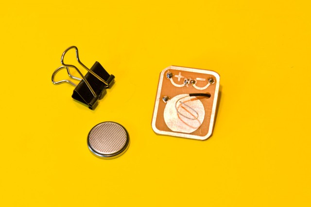
Here’s the back of the PCB. You can see how the board has been etched to leave just the copper traces to complete the circuit. (The ring around the edge is just a guide for the cutting and sanding.)

Zoom PCB

Here’s the front of the PCB. You can see the LED, resistor, and the wire that leads to the back through the hole which serves as the battery connector. And of course the binder clip holds the battery in place.

Zoom PCB

You can remove the arms of the binder clip if you want to stand the PCB up, attach it to something, or just be more streamlined.

Zoom PCB

Zoom PCB

PCB Wearable

And hey, with the addition of the magnet you can even turn it into a wearable! Be the envy of the Zoom After Party (wait, is there one?) with your flickering, flashing, or constantly lit LED PCB!

This is just one post in a series, check out the other posts as well:

Categories
Uncategorized

Craft Hammers

Craft Hammer

I made a few Baltic Birch hammers (laser etched and laser cut) as a follow-up to my CRAFT Screwdriver (which was just vinyl cut.)

Craft Hammer

Here’s the design and mock-up. I use Inkscape for the design process, and occasionally create the mock-up images using Photoshop.

Craft Hammer

This hammer is not the size of a normal hammer. It’s over 400mm long, which (being nearly 16 inches) is big. Why such a big hammer? Because, reasons…

Craft Hammer

Actually, this specific hammer was given to Frankie Flood, who has had a huge influence on my work the past few years. Since he’s leaving Milwaukee, I wanted to give him something that would be suitable for hanging on the wall in his new studio.

Craft Hammer

HAMMERS!!!

Categories
Uncategorized

Teensy LC BOB v1.3

Teensy LC BOB v1.3

Update: If you’d like one of these boards, there’s a newer version of this board, and you can purchase it on Tindie.

Good News, Everyone! The new Teensy LC break-out board is ready! Yes, we’re now at version 1.3 of the Teensy LC BOB.

Preview

I’ve made a few changes since version 1.2. I moved the traces from the top to the bottom (how did I miss that!?) and I added an extra ground line so that you can connect a bunch of screw terminals to the ground row even if you don’t solder in header pins at the end of the board and only do the sides. (This also comes in handy if using the Teensy Audio Adaptor Board.)

I’ve also lengthened the board a bit, and added a fifth hole, and here’s why…

Installed

For a recent project I discovered that the USB cable was able to rip the USB connector right off the Teensy if hit, twisted, or yanked in the wrong direction. The fifth hole is for adding a piece (wood? plastic?) by screwing it into the bottom and then looping a zip tie around the USB cable for strain relief.

USB mock-up

I scanned in a Micro USB cable and placed it over an image of the board to figure out spacing. It should work. I may end up 3D modeling the piece that holds the USB cable in place.

As I use the boards more I may find other improvements along the way. Also, I’m now able to load in custom images and graphics onto the PCB, so I’m already scheming for my next OSH Park project.

Categories
Uncategorized

Arts+Tech Night at UWM

Arts+Tech Night

I mentioned back in February that I’ve been teaching a Physical Computing class at UWM called “Electronics and Sculpture” this semester. So I’ve basically been showing students how to integrate microcontrollers into their artwork. (Arduino is the order of the day, though I’ve got one student exploring ATtiny85 chips.)

Students have been working on their final projects, using techniques they’ve learned all semester, and they’ll have their work on display for the public at Arts+Tech Night happening 6pm-9pm, Wednesday, May 18th, 2016. Come on down and check it out. Most of my students will be on the 4th floor in the center area. (Maybe your friends are already going!)

mike-light

(There is a web site for ATN but sadly, despite my best efforts, It has not been updated this time around.)

Categories
Uncategorized

Learn to Solder Kit (Part IV)

This installment of the Learn to Solder Kit series will focus on the cutting and sanding of the PCBs we’ve been creating. This is the loud and messy part. (Check out Part I, Part II, and Part III if you haven’t seen them.)

pcb-cut-sand-0316

We start with taking one of the larger board to the bandsaw and cutting apart the six boards. (The bandsaw, like many of my tools, belonged to my father. It’s quickly become one of the most used tools in the shop, right after the drill press.)

pcb-cut-sand-0318

In an earlier revision of the board I left very little room to cut things apart. I just barely had the width of the saw blade, so as I etched more boards, I revised the design and increased the space to make things a bit easier.

pcb-cut-sand-0324

One large board cut down to six individual boards. I also cut off any excess on the edges to make the sanding process that comes later easier.

pcb-cut-sand-0329

You can see that straight lines aren’t the order of the day, which is fine. Our goal with the cutting apart is just to get things cut apart. We’ll straighten out the edges later…

pcb-cut-sand-0328

Here’s a big pile of individual boards ready to have their edges cleaned up. You’ll noticed the thin edge pieces that got cut off as well, which saves us time (and dust!) when sanding.

pcb-cut-sand-0337

Using the disc sander is pretty quick, but it’s also dusty, and probably my least favorite part of the process. Also, the disc sander is a cheap model someone gave me, and while I’m thankful for it, it’s loud and vibrates way more than it should.

pcb-cut-sand-0340

Cleaned up edges, courtesy of the disc sander. We’ve finally got those straight lines we didn’t get on the bandsaw.

pcb-cut-sand-0341

Once we have those nice clean sides on the board it’s time to round the corners. This is the part that requires a some finesse to make it nice. Sometimes I get great results, and sometimes I go quickly and say “good enough!” because I’ve got 20 more boards to do.

Oh, you might also notice a bit of “fuzz” on the edges…

pcb-cut-sand-0347

Here’s the back side of the board, where you can more clearly see the fuzz left from the sanding process. This is easy to clean up.

pcb-cut-sand-0350

We just lightly clean the fuzz off using the belt portion of the sander. Every now and then I drop a board while doing this and have to fish it out of the exhaust port. It’s annoying.

pcb-cut-sand-0355

Here’s our nice clean board. It’s been cut apart from the larger board, and then sanded to get straight edges, given rounded corners, and cleaned up of any fuzz. Ready to go!

pcb-cut-sand-0360

A big pile of finished boards at the end of the night. I can only take so much sanding in one session. Right now I’ve got 40 completed boards, and another 25 that need to be sanded. With a goal of 100 total I’ll need to etch, drill, cut, and sand about 6 more large boards (to get 36 individual PCBs) in the next two weeks in time for the Maker Plaza at the Zoom Milwaukee Symposium!

This is just one post in a series, check out the other posts as well: