Categories
Uncategorized

Learn to Solder Kit (Part II)

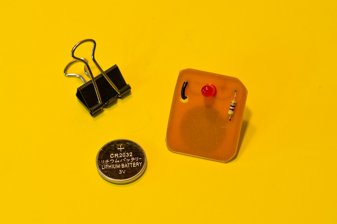
If you haven’t read the first installment, check out Learn to Solder Kit (Part I) to get up to speed.

Since I’m etching my own boards, there’s a number of steps in the process. I’ve covered it all in the photos below, and I’ll add in a bit of text to explain things.

pcb-etching-0180

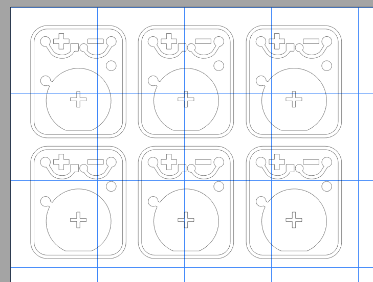
I start with cutting vinyl on a Silhouette Cameo. Any vinyl cutter will do, this just happens to be the one I have at home. (We have the same model at Milwaukee Makerspace, and the DCRL has a much larger vinyl cutter.)

pcb-etching-0182

The vinyl after being cut. I’m using old scraps of various sizes, and I’ve got an old blade, and an old cutting mat, and sometimes it cuts almost all the way through the vinyl, but for this application it all works out fine.

pcb-etching-0183

Next is weeding, or removing all of the bits of vinyl we don’t need. I tend to use an X-ACTO knife to pick and grab off the pieces. It works well for tiny things like this.

pcb-etching-0189

The vinyl is all weeded and we’ve got a piece of transfer paper ready to apply. (The transfer paper sticks to the top of the vinyl just enough to pull it from the backing sheet.)

pcb-etching-0191

Once the transfer paper is down on the vinyl I press hard and rub it on good so it’ll adhere to all the tiny pieces.

pcb-etching-0192

Peeling back the transfer paper is best done slowly, checking to see if any vinyl doesn’t get pulled up. Occasionally you have to press it down again to grab a piece of vinyl that didn’t stick properly.

pcb-etching-0195

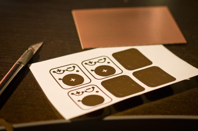
Here’s the transfer paper with all the bits of vinyl stuck to it. At this point we can stick it down onto the copper board that will be our PCB. (I usually give the copper board a light scrubbing with steel wool before sticking the vinyl on.)

pcb-etching-0199

Once again we press hard and rub the transfer paper onto the copper board, and then peel back slowly making sure we don’t lose any tiny bits of vinyl in the process…

pcb-etching-0213

And here’s our copper board with the vinyl resist in place. The vinyl works as a mask to protect the copper from being etched away. Anywhere you don’t see vinyl you won’t see copper when we are done.

pcb-etching-0221

Over to the PCB etching machine! It’s what we might call “janky” because I constructed it very quickly to etch some PCBs and it worked well enough that I never built a better one. I did upgrade from a servo to a DC gear motor at some point, but the bearings are still riding on smooth rods much smaller than they should be. Again, it works, so I don’t mess with it.

pcb-etching-0223

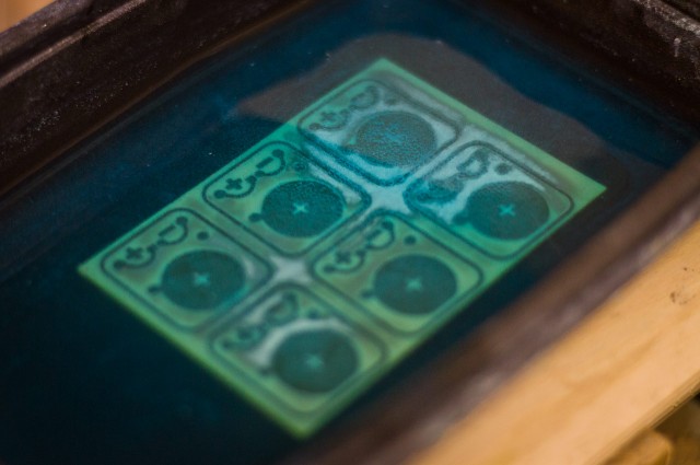
After adding equal parts hydrogen peroxide and vinegar to the tank (which is a food container from Noodles & Company) I put the copper board into the solution…

pcb-etching-0224

The board tends to float at first so I push it down with a brush. (I also use the other end of the brush to wipe away the solution while the board is etching.)

pcb-etching-0230

Yes, my chemical mix is hydrogen peroxide and vinegar, with a dash of salt. There are other things you can use, but this combo isn’t really dangerous, and can be easily disposed of by pouring down the drain with plenty of water. If I can avoid harsh acids, I will. It does take a bit longer to etch, but that’s where the salt comes in.

pcb-etching-0232

Once I start the agitation process to keep the board and liquid moving back and forth, I throw a bit of salt into the mix, which activates things and tends to foam up a bit. The foam means it’s working!

pcb-etching-0242

This is about 45 minutes into the etching process. You can see that the copper is nearly gone all around the edges, but not as much in the middle.

pcb-etching-0257

Here’s the 50 minute mark after adding a pinch more salt to the mix. It’s mostly etched but still has more copper to eat.

pcb-etching-0258

At about an hour and ten minutes the board is fully etched. Time tends to vary depending on if I reuse the solution or start fresh. I’m typically not in a hurry and tend to reuse solution a lot, which does take longer, but means I’m wasting less solution.

pcb-etching-0262

Once the board is done I pull it out and use a razor blade to gently remove the pieces of vinyl. They tend to come off fairly easy, but they are wet and stick to everything, including fingers, razor blades, the board, and anything else within 50mm of the work area.

pcb-etching-0265

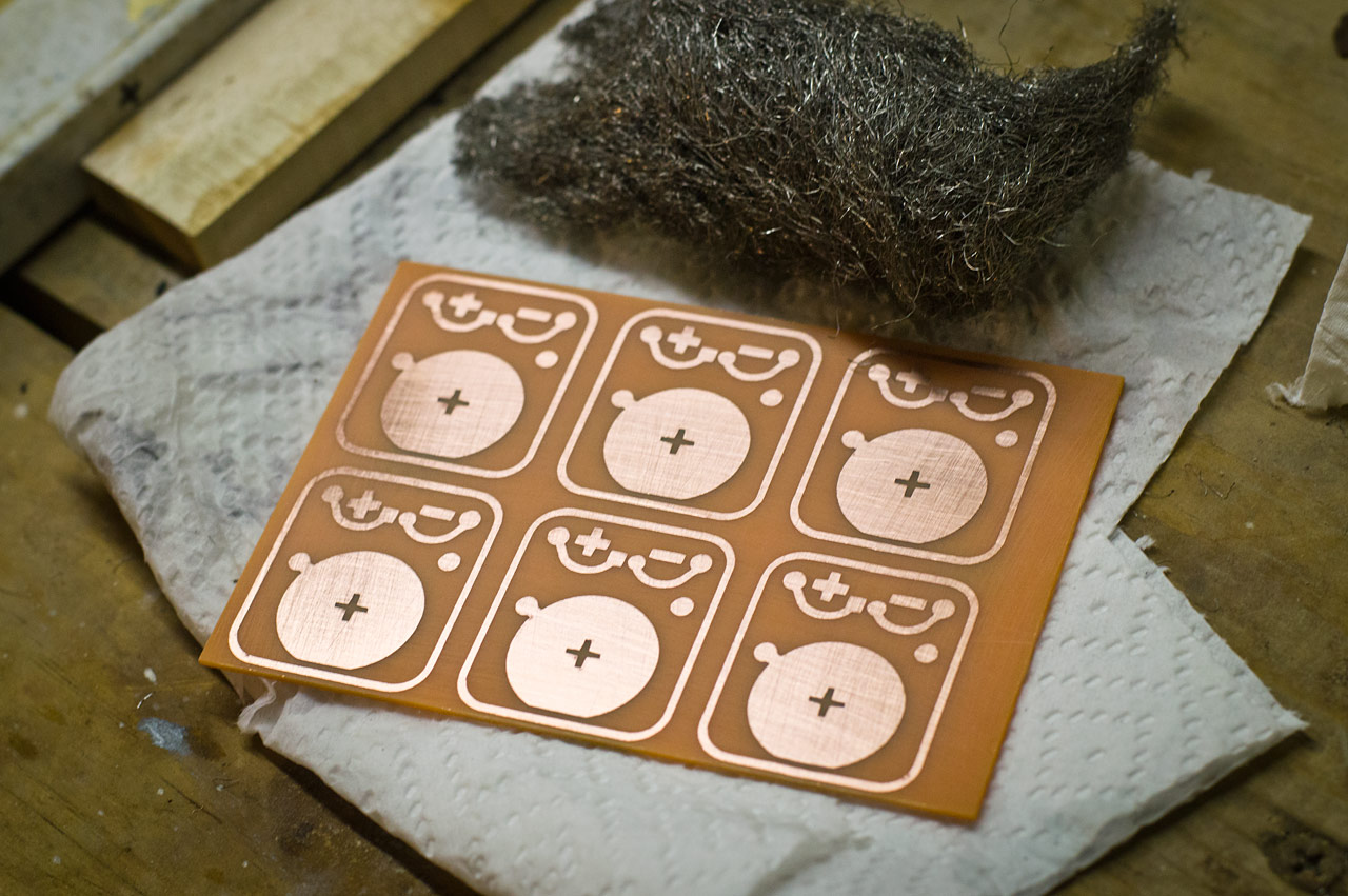
After the vinyl is removed I wash and rise the board and then dry it and give it another quick scrub with steel wool.
We’ve now got a PCB, or a “Printed Circuit Board” as they are commonly known. (Somehow almost everything I do revolves around “printing” somehow…)

That covers the etching, so the next steps are to drill all the holes and to cut the boards apart.

Oh, you’ll also want to check out this mesmerizing video featuring the PCB Etching Machine in action. Agitation is the name of the game!

This is just one post in a series, check out the other posts as well:

Categories
Uncategorized

Learn to Solder Kit (Part I)

Zoom Milwaukee

Some of the folks I know at UWM are putting on a symposium called Zoom Milwaukee, which will focus on craft, culture, innovation and making. They’ll also have a Maker Plaza which they described as a sort of “Mini Maker Faire” environment. They also asked if I could do a hands-on make-and-take workshop, so I decided to do a Learn to Solder activity. I’ll attempt to walk through my process for developing it in this and future posts.

Fritzing

Since I’ve been using Fritzing to design PCBs I thought I would play around with some ideas. The basic Learn to Solder kit tends to revolve around an LED or two, a battery, and maybe a pin of some sort. They are typically wearable badges. (Here’s a prototype and final board from Milwaukee Makerspace. Maker Shed has some nice ones as well.)

Fritzing

Oh, and ignore than second resistor, that was just to determine some spacing issues. Same with the battery. Fritzing isn’t the greatest tool for PCB design, but it (mostly) works and it’s simple to use. I did end up checking a version of this board with OSH Park to determine pricing and specs, but eventually I decided that this isn’t the board I wanted fabbed, and with a deadline quickly approacing I decided to go another direction.

I did use the work from Fritzing as the basis of the design I did in Inkscape though… And why Inkscape? Because my plan was to create this kit as cheaply as possible, which meant I’d be etching my own boards. I visited my friends over at ebay.com and started searching for components. I’ve ordered blank copper boards before so I got a bunch of those, and some LEDs and the appropriate resistors, and some batteries.

PCB versions

The evolution of design. The nice thing about etching your own boards is that you can do a few, test them out, and make some changes, and do it all again. You can do these revisions fairly quickly and very cheaply. Here’s a number of my design tweaks as I etched boards. Some things got larger, some got smaller. I needed something I could easily cut from vinyl using a Silhouette Cameo, so super-small pieces had to be avoided. The minus sign caused the most problems. You can see it change in size as we go. (The outline around each board is to assist with cutting them out.)

PCBs

Here’s the design 6-up so I could fill a blank copper board for etching. Weeding the vinyl wasn’t a nightmare, but pulling all the tiny pieces off the final board wasn’t fun.

Silhouette

The copper boards I used are about 4″ x 3″ so the 6-up layout I did was loaded into the Silhouette Studio software to cut the vinyl. This worked well as I tend to have a lot of little scraps from bigger jobs to use up. (I did mention doing this on the cheap, didn’t I?)

Vinyl on copper

Here’s a shot of one of the earlier design revisions with the vinyl applied to the copper board pre-etching stage. Once the etching is done all the copper you can see will be gone, leaving copper just where the vinyl is. The vinyl is the resist in this process.

This is just one post in a series, check out the other posts as well:

Categories
Uncategorized

Wood/Metal Hammers

Wood/Metal Hammers

While you may be familiar with my hammer-related work, I typically lean towards different materials, such as concrete, or paper, pixels, and plastic, or perhaps ice? And yes, of course wood

This time I returned to wood, but decided to give it a metal look. The above is a 12″x12″ sheet of wood with 1/8″ laser-cut hammers attached to it.

Screen Printed Hammers

The artwork came from Kathy who created it for a screen printing demo I did at Milwaukee Makerspace a while back. We made a vinyl cut stencil for the screen and then I showed people how to print it on a shirt.

Wood/Metal Hammers

I’ve used metallic paint before on wood, but I think a few different colors mixed together turned out well. I tried to keep things rough looking and was a bit loose and crazy with the paint.

Wood/Metal Hammers

Splotches were intentional, of course… I may try a few more experiments with metallic spray paint on wood. I think it gives a good look. I’m wondering if I can layer polyurethane or another sealer on top if it as well.

Wood/Metal Hammers

Categories
Uncategorized

Traffic Lights

Traffic Lights

I recently repaired the traffic and walk signals at BBCM. The system had been running on a PLC (Programmable Logic Controller) which failed, and rather than find the proprietary programming cable and find and install the PLC Windows software, I decided to just put an Arduino and relay control board in place.

Arduino and Relay Board

I had a Teensy++ 2.0 I had pulled from another exhibit during an upgrade, and an 8 channel relay board on hand. These relay boards come in different configurations from 1, 2, 4, 8, and even 16 relays. Since I really only needed 5 relays (and 5 pins) I could have used an ATtiny85, but I had the Teensy++ 2.0 readily available. The wiring is all done using female to female jumper wires.

Traffic Controller

I mounted everything to a piece of scrap MDF and added mounting holes to that, with the idea that we’d screw the whole thing directly into the wall. The relay board has mounting holes, but the Teensy does not. That’s probably my one complaint about the Teensy boards, is that mounting them isn’t always easy. My Teensy BOB has mounting holes, but for mounting this Teensy++ 2.0 I just used some 3M™ VHB™ tape. (The “VHB” stands for “Very High Bond”). And yes, there are a few 3D printed parts on there. At some point I should make a 3D printed holder/mount for a Teensy++ 2.0

Labels

I try to label things clearly. If I look at this thing in 6 months, or 2 years, or someone else has to look at it, I want it to be somewhat apparent what is what, so there’s not a lot of guesswork as to what is going on. I included a label with the name of the Arduino sketch, and I always like to label power supplies. Sometimes we use 5 volts, and sometimes 12 volts, and they typically have tiny hard to read type printed on the side of the power supply that you can’t see when it’s plugged in.

The one thing I should start to add to the labels is the URL of the wiki page where the thing is documented. (Next time I’ll do this.)

Controller Mounted

Here’s the controller mounted. It’s not pretty. We ended up re-using the mount that the PLC was in, rather than screwing it right into the wall. In my defense, we did this repair on the floor during open hours, and it’s mounted high on a wall behind a TV. Does it work? Yes… Is it awesome, no… but again, it totally works.

The wiring for the lights was all 12 VDC, not 110 VAC, so those thin gauge wires are fine. Also, they were labeled, which was handy. (Thanks previous person who worked on this and labeled things!)

Wiring Diagram

I try to create wiring diagrams for everything. I use Fritzing because it’s simple and awesome and open and free. I often don’t find the components I need, but you can always just use a note and some text.

Here’s the script/sequence for the lights:

  1. Green Light is ON
  2. Walk Light is ON
  3. Waiting 4 seconds…
  4. Walk Light is OFF
  5. Don’t Walk Light is BLINKING (for 5 seconds)
  6. Green Light is OFF
  7. Don’t Walk Light is ON
  8. Yellow Light is ON
  9. Waiting 4 seconds…
  10. Yellow Light is OFF
  11. Red Light is ON
  12. Waiting 6 seconds…
  13. Red Light is OFF
  14. Don’t Walk Light is OFF
  15. (Repeat sequence)

I wrote this up to figure out how to program things. I find it helpful to plan things out before I start writing the code.

At first I just talked through the light sequence with someone and we made some assumptions about how it worked. We were slightly wrong, which I discovered when I dug a bit deeper into traffic lights and walk signals. I read at least some of the (very long) Wikipedia page on Traffic Lights. I also hunted for other info, and found some on the Signals FAQ page on the Minnesota Department of Transportation web site. (As I mentioned with the 911 Phone I really do aim for an accurate and realistic experience with these things.)

It’s been a few weeks and the lights have been working fine. Hopefully that will continue to be the case. If something does stop working we’ll open a ticket for it so we have a record. And yes, we do use an issue tracker for our museum exhibits… doesn’t everyone?

Categories
Uncategorized

Hot Dog on a Spring on a Motor

Hot Dog on a Spring on a Motor

It’s been a lot of fun teaching Electronics and Sculpture, and weird things happen sometimes, so I thought I’d take the time to explain a weird thing, and how it happened. The photo above is a kinetic sculpture titled “Hot Dog on a Spring on a Motor”.

Steak Ballet

The photo above is a kinetic sculpture titled “Steak Ballet”. It was created by Atticus, one of the students in the class. When you open the box, the steak (not a real steak) spins around. It’s like a music box, without music, and with meat. (But not real meat.)

During critique we started coming up with a few crazy ideas, and someone, I don’t know if it was me, or if it was Mike, came up with idea of a hot dog, on a spring, that spins around. I honestly can’t remember if one person came up with it, or it was collaborative, but it became a running joke during critique… and in a few classes afterwards.

Hot Dog on a Spring on a Motor

Steak Ballet was the third project of the semester. By the fourth project (the mid-term) the hot dog on a spring thing was sort of a regular joke. The mid-term projects were awesome, and I was really proud of the work my students did, so I decided to reward them by building something and showing it to them… thus “Hot Dog on a Spring on a Motor” was born. And I gave credit to the class on the bottom of the piece.

Hot Dog on a Spring on a Motor

Now, this also all came together for another weird reason… Joe at BBCM brought a bunch of hot dogs into my office and I asked if I could borrow one. Also, Joe knows Atticus and they used to work together. Weird!

And yes, this does continue some of the ideas I was playing with when I created the Pizza Bagel Bot for a robot battle last year.

Hot Dog on a Spring on a Motor

Here’s a quick (poor quality) video of the Hot Dog on a Spring on a Motor. (At least it’s not a Vertical Video!)